Method of determining cardiac indicators

a cardiac indicator and cardiac indicator technology, applied in the field of non-invasive monitoring, can solve the problems of significant risks to patients, and the inability to routinely use the pulmonary artery catheter, so as to improve the function of left ventricular, determine the effectiveness of cardiac therapy in an individual, and achieve effective cardiac therapy

Active Publication Date: 2009-05-05
THE RES FOUND OF STATE UNIV OF NEW YORK
View PDF5 Cites 6 Cited by
  • Summary
  • Abstract
  • Description
  • Claims
  • Application Information

AI Technical Summary

Benefits of technology

[0011]The heart beat events that can be determined by the computer running the software may include the V waveform, time of the occurrence of the peak of the V waveform, the pressure at the time the peak occurs, the time at which the slope of the V waveform changes from negative to non-negative, and the time that the aortic valve of the person closes. By determining these data, the software may enable the computer to determine the left ventricle isovolumetric relaxation time (LVIVRT). The LVIVRT may be determined by measuring the change in time between closure of the aortic valve and the time of the occurrence of the peak of the V waveform. The software may also enable to computer to determine the average slope of that part of the V waveform that immediately follows the peak of the V waveform by determining the change in pressure from the time of occurrence of the peak of the V waveform to the time at which its slope first becomes non-negative, and dividing that pressure change by the change in time between the occurrence of the peak of the V waveform and the time at which the V waveform first becomes non-negative. The software may further enable the computer to normalize the V waveform negative slope value of the individual to a selected frequency of heartbeats, such as one beat per second.

Problems solved by technology

Heart failure has previously been thought to be due exclusively to poor contractility of ventricles.
More recently it has come to be understood that diastolic dysfunction can be a significant factor in heart failure.
Measurement of diastolic dysfunction can be performed using invasive techniques, but there are significant risks to the patient.
However, the risks to the patient from using the pulmonary artery catheter preclude routine use.
However, echocardiography is difficult to perform, less accurate, and impractical to use for longer than a few minutes at a time.
Consequently, it is difficult to obtain an accurate evaluation of the heart using esophageal echocardiography.

Method used


Image

  • Method of determining cardiac indicators
  • Method of determining cardiac indicators
  • Method of determining cardiac indicators

Examples


Embodiment Construction

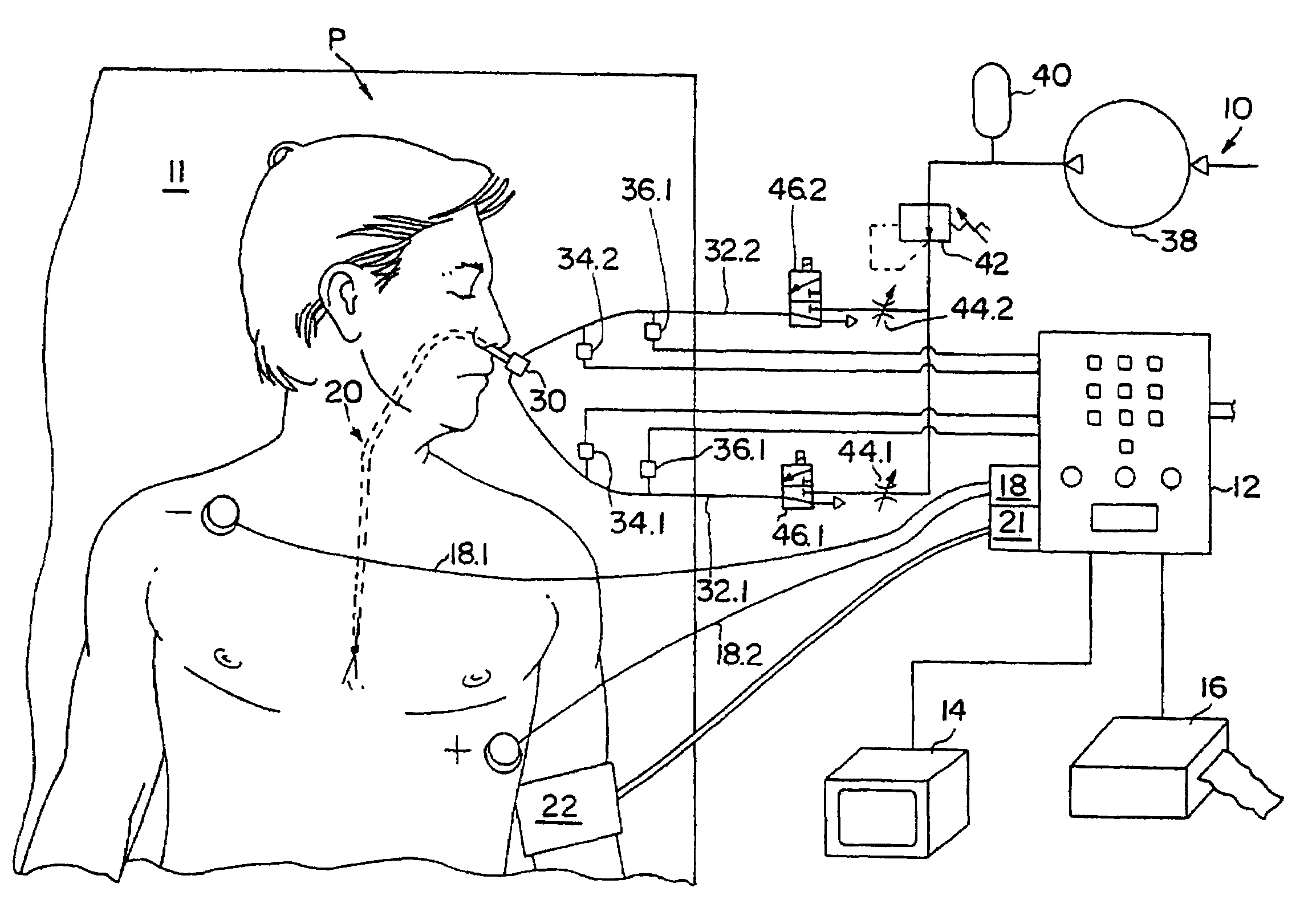
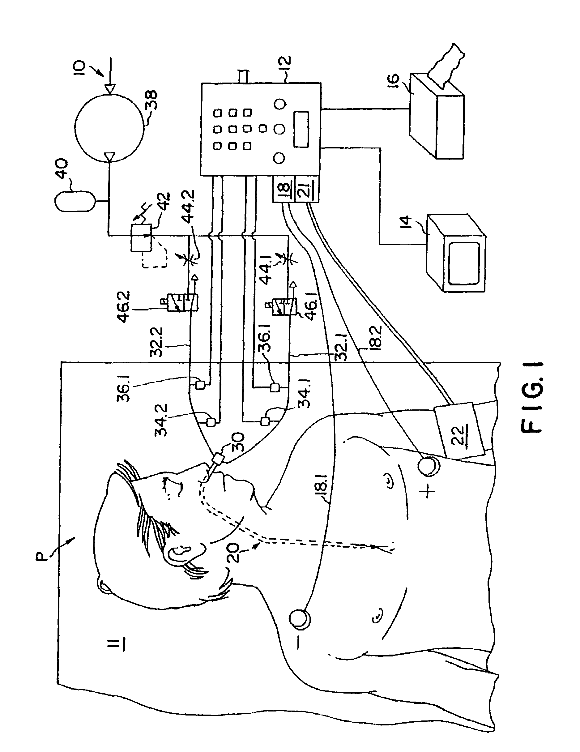
[0036]Referring to FIGS. 1 to 3, the cardiac performance apparatus for noninvasive monitoring, indicated generally at 10, is shown associated with a person P, who may be a patient in a cardiac care setting. The person P is shown in a supine position on a hospital bed, gurney, operating table or the like, which support is indicated at 11. The apparatus includes, as its principal components, a computer including controlling and information processing means 12, such as a computer, and information display apparatus including a monitor 14 and a recorder 16. The controlling and information processing means, which includes a computer, further includes an electrocardiograph (ECG) 18 conventionally having leads 18.1 and 18.2 and a ground lead (not shown), and an automatic sphygmomanometer 21 which is interconnected with a blood pressure cuff 22. The cardiac performance apparatus for non-invasive monitoring additionally includes an esophageal catheter, indicated generally at 20. The automatic...


PUM


Abstract

A system and method for determining indicators of left ventricular function, and for determining the effectiveness of a cardiac therapy are disclosed. The indicators of left ventricular function can include isovolumetric relaxation time and the negative slope of a V wave obtained from measuring changes in left atrial pressure during diastole. The apparatus may include a catheter comprising an inflatable balloon for insertion into the esophagus of an individual, a compressor device for pressurizing the balloon, and a means for sensing and recording pressure changes on the balloon.

Description

[0001]This application claims priority to U.S. Provisional Patent Application Ser. No. 60 / 691,561, filed Jun. 17, 2005, the entire disclosure of which is incorporated herein by reference.FIELD OF THE INVENTION[0002]The present invention relates generally to a method for noninvasive monitoring of one or more cardiac performance parameters, and more particularly to a method for monitoring cardiac performance associated with diastolic dysfunction.BACKGROUND OF THE INVENTION[0003]Heart failure has previously been thought to be due exclusively to poor contractility of ventricles. More recently it has come to be understood that diastolic dysfunction can be a significant factor in heart failure. Diastolic dysfunction is believed to account for as many as 40% of all cases of congestive heart failure (CHF). One indicator of diastolic dysfunction is the time during which the left ventricular muscle relaxes following a contraction. The portion of the cardiac cycle between the end of left ventr...

Claims


Application Information

Patent Timeline
Patent Type & Authority Patents(United States)
IPC IPC(8): A61N1/362
CPCA61B5/02158A61B5/6853A61B7/023A61B7/026A61B5/022A61B5/0421A61B5/0422A61B5/0452A61N1/0517A61B5/7239A61B5/285A61B5/287A61B5/349
Inventor HICKEY, DONALD D.
Owner THE RES FOUND OF STATE UNIV OF NEW YORK
Why Eureka
Try Eureka