
Using image and laser constraints to obtain consistent and improved pose estimates in vehicle pose databases

a technology of laser constraints and image and laser constraints, applied in image enhancement, navigation instruments, instruments, etc., can solve problems such as inconsistent gps signals, inaccurate or missing gps information, and drift, and achieve accurate alignment constraints and minimize the total energy value of constraints

Active Publication Date: 2013-05-07
GOOGLE LLC
View PDF17 Cites 22 Cited by
  • Summary
  • Abstract
  • Description
  • Claims
  • Application Information

AI Technical Summary

Benefits of technology

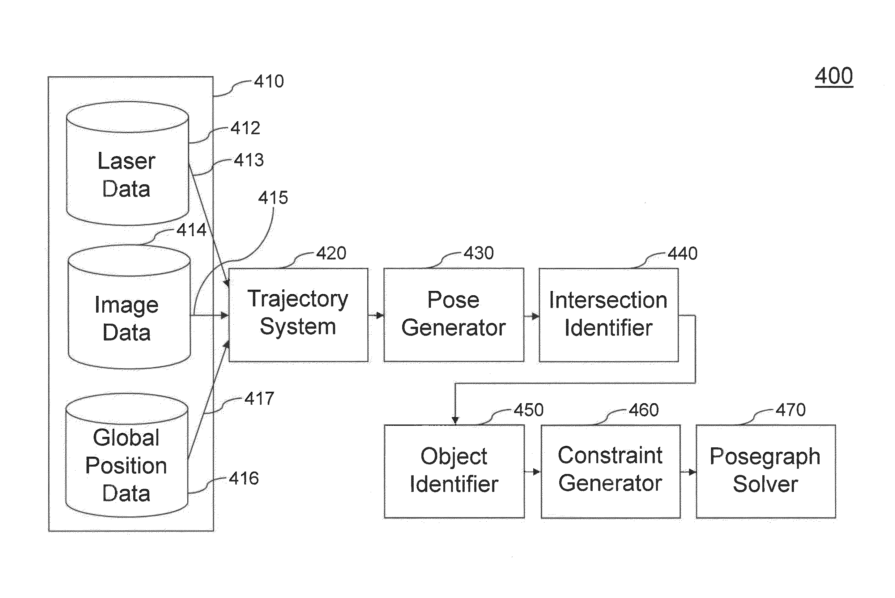
[0011]According to another embodiment of the present invention, a system for pose generation consists of a trajectory system, a pose generation system, an intersection extractor, an object identifier, a constraint generator, and a posegraph solver. The trajectory system identifies a number of trajectories based on input positional data of a bounded area. The pose generation system generates one or more poses based on the trajectories. The intersection extractor identifies one or more possible intersections in the one or more poses. The object identifier identifies an object pair for each possible intersection that represents two positional points at each possible intersection. The constraint generator computes and applies one or more intersection constraints to generate an energy value for each object pair based on their geometric relationship. The posegraph solver minimizes a total energy value including all of the individual energy values associated with each object pair by modifying one or more poses.

Problems solved by technology

Drift occurs due to measurement errors associated with relative pose sensors, e.g., laser, wheel, odometry, and inertial measurement unit data.
Global positioning system (GPS) sensors provide absolute pose information that decreases the amount of drift, but GPS information can be itself very inaccurate or missing, especially in urban canyons.
However, GPS signals can be inconsistent as the satellite positions are time dependent and can produce large errors where the satellite signal is reflected off of an obstacle, especially in an urban setting.
IMU and wheel encoder sensors also have inherent measurement errors.
Therefore, the resulting set of pose trajectories from each type of system can be inconsistent, as well as inconsistent with one another.

Method used


Image

  • Using image and laser constraints to obtain consistent and improved pose estimates in vehicle pose databases
  • Using image and laser constraints to obtain consistent and improved pose estimates in vehicle pose databases
  • Using image and laser constraints to obtain consistent and improved pose estimates in vehicle pose databases

Examples


Embodiment Construction

[0027]While the present invention is described herein with reference to illustrative embodiments for particular applications, it should be understood that the invention is not limited thereto. Those skilled in the art with access to the teachings provided herein will recognize additional modifications, applications, and embodiments within the scope thereof and additional fields in which the invention would be of significant utility.

[0028]The embodiments described herein are referred in the specification as “one embodiment,”“an embodiment,”“an example embodiment,” etc. These references indicate that the embodiment(s) described can include a particular feature, structure, or characteristic, but every embodiment does not necessarily include every described feature, structure, or characteristic. Further, when a particular feature, structure, or characteristic is described in connection with an embodiment, it is understood that it is within the knowledge of one skilled in the art to affe...


PUM


Abstract

A system for pose generation consisting of a trajectory system, a pose generation system, an intersection extractor, an object identifier, a constraint generator, and a posegraph solver. The trajectory system identifies a number of trajectories based on input positional data of a bounded area. The pose generation system generates one or more poses based on the trajectories. The intersection extractor identifies one or more possible intersections in the one or more poses. The object identifier identifies an object pair for each possible intersection that represents two positional points at each possible intersection. The constraint generator computes and applies one or more intersection constraints to generate an energy value for each object pair based on their geometric relationship. The posegraph solver then minimizes a total energy value by modifying one or more poses and then generates an improved set of pose trajectories based on the modified one or more poses.

Description

CROSS-REFERENCE TO RELATED APPLICATIONS[0001]This application is a continuation of U.S. patent application Ser. No. 12 / 882,063, filed Sep. 14, 2010, which is incorporated herein by reference in its entirety.BACKGROUND[0002]1. Field of the Invention[0003]Embodiments of the present invention relate to generating optimized loop-closed pose estimates.[0004]2. Related Art[0005]The use of lasers in robotics became popular in the context of estimating the path of a robot equipped with laser sensors, where detecting that the robot has re-visited a known area can be used to decrease the amount of drift that accumulates during pose estimation. Drift occurs due to measurement errors associated with relative pose sensors, e.g., laser, wheel, odometry, and inertial measurement unit data. Global positioning system (GPS) sensors provide absolute pose information that decreases the amount of drift, but GPS information can be itself very inaccurate or missing, especially in urban canyons. The concep...

Claims


Application Information

Patent Timeline
Patent Type & Authority Patents(United States)
IPC IPC(8): G06K9/00G06K9/46G06F17/10
CPCG06K9/00664G06T7/0042G06T2207/30241G06T7/73G06V20/10
Inventor ANGUELOV, DRAGOMIRFRUEH, CHRISTIANAGARWAL, SAMEER
Owner GOOGLE LLC
Learn More