Apparatus and method for optical interrogation
a technology of optical interrogation and apparatus, applied in the field of apparatus and optical interrogation apparatus, to achieve the effect of convenient operation
- Summary
- Abstract
- Description
- Claims
- Application Information
AI Technical Summary
Benefits of technology
Problems solved by technology
Method used
Image

Examples
Embodiment Construction
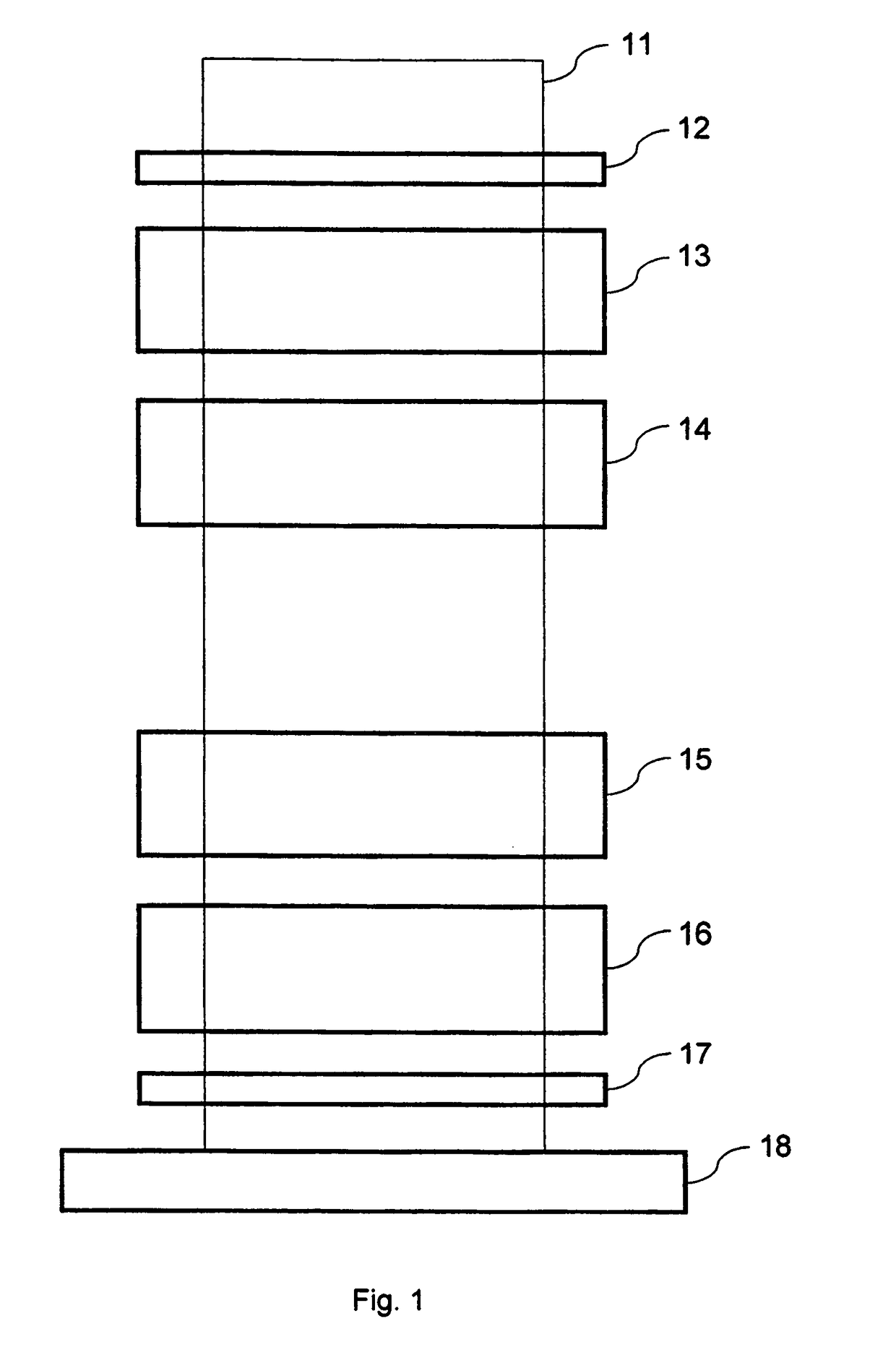
[0027]FIG. 1 is a schematic arrangement of components for producing the partial shear formatted probe beam according to one embodiment of the invention. The formatted probe beam is represented at 11 and in the illustration simply illustrates the direction of the formatted probe beam through the various elements 12 to 18. It should be understood that the blocks 12 to 18 represent the optical elements described and are not illustrative of the size or physical characteristics of those components. Also, the elements may be spaced from one another, but are preferably in proximity in an integrated optical assembly as will be illustrated in more detail below. In the apparatus of FIG. 1 the probe beam, as it is formatted, undergoes splitting and displacement of the split beams. Accordingly the line 11 indicates only a general direction of the probe beam through the various elements in FIG. 1.
[0028]The apparatus may be operated with 11 oriented either vertically, as suggested by the figure, ...
PUM
 Abstract
Description
Claims
Application Information
 - R&D
- Intellectual Property
- Life Sciences
- Materials
- Tech Scout
- Unparalleled Data Quality
- Higher Quality Content
- 60% Fewer Hallucinations
Browse by: Latest US Patents, China's latest patents, Technical Efficacy Thesaurus, Application Domain, Technology Topic, Popular Technical Reports.
© 2025 PatSnap. All rights reserved.Legal|Privacy policy|Modern Slavery Act Transparency Statement|Sitemap|About US| Contact US: help@patsnap.com