
Method and device for image filtering

a filtering and image technology, applied in the field of communication technologies, can solve the problems of image quality degradation, differences between display principles of television and computer, television and computer system not being compatible with display, etc., and achieve the effect of avoiding image flickering

Active Publication Date: 2013-07-16
HUAWEI TECH CO LTD
View PDF20 Cites 0 Cited by
  • Summary
  • Abstract
  • Description
  • Claims
  • Application Information

AI Technical Summary

Benefits of technology

The solution effectively avoids image flickering by using transparency-based filter coefficients, enhancing visual quality by accounting for pixel transparency variations, and allowing for more complex visual effects.

Problems solved by technology

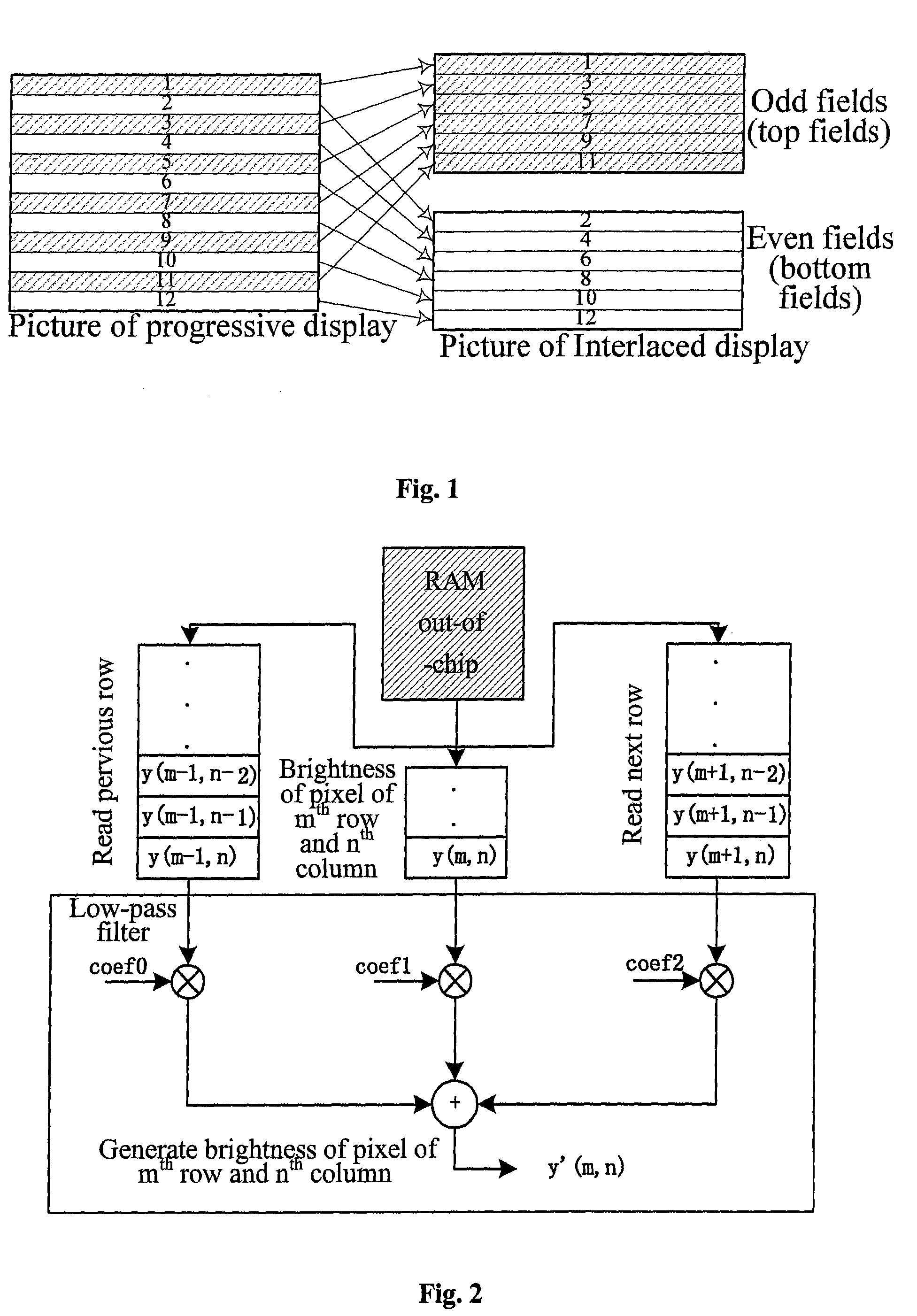
However, when an image edited on a computer is to be displayed in an interlaced way on a television, quality of the image tends to be degraded due to a flicker feeling with respect to the image.
This results from differences between display principles of the television and the computer, where the progressive display is used for the computer, and the interlaced display is used for the television.
As can be seen from above, systems of televisions and computers are not compatible in display.
However, markets of televisions and computers have already become confluent.
The method using the vertical low-pass filtering is disadvantageous in that an effect of a pixel transparency (an Alpha value) on anti-flickering has not been taken into account.
If only vertical filtering of brightness is performed here, then the flickering due to a difference between the transparencies can not be avoided and hence such a flickering still fails to be avoided effectively.

Method used


Image

  • Method and device for image filtering
  • Method and device for image filtering
  • Method and device for image filtering

Examples


first embodiment

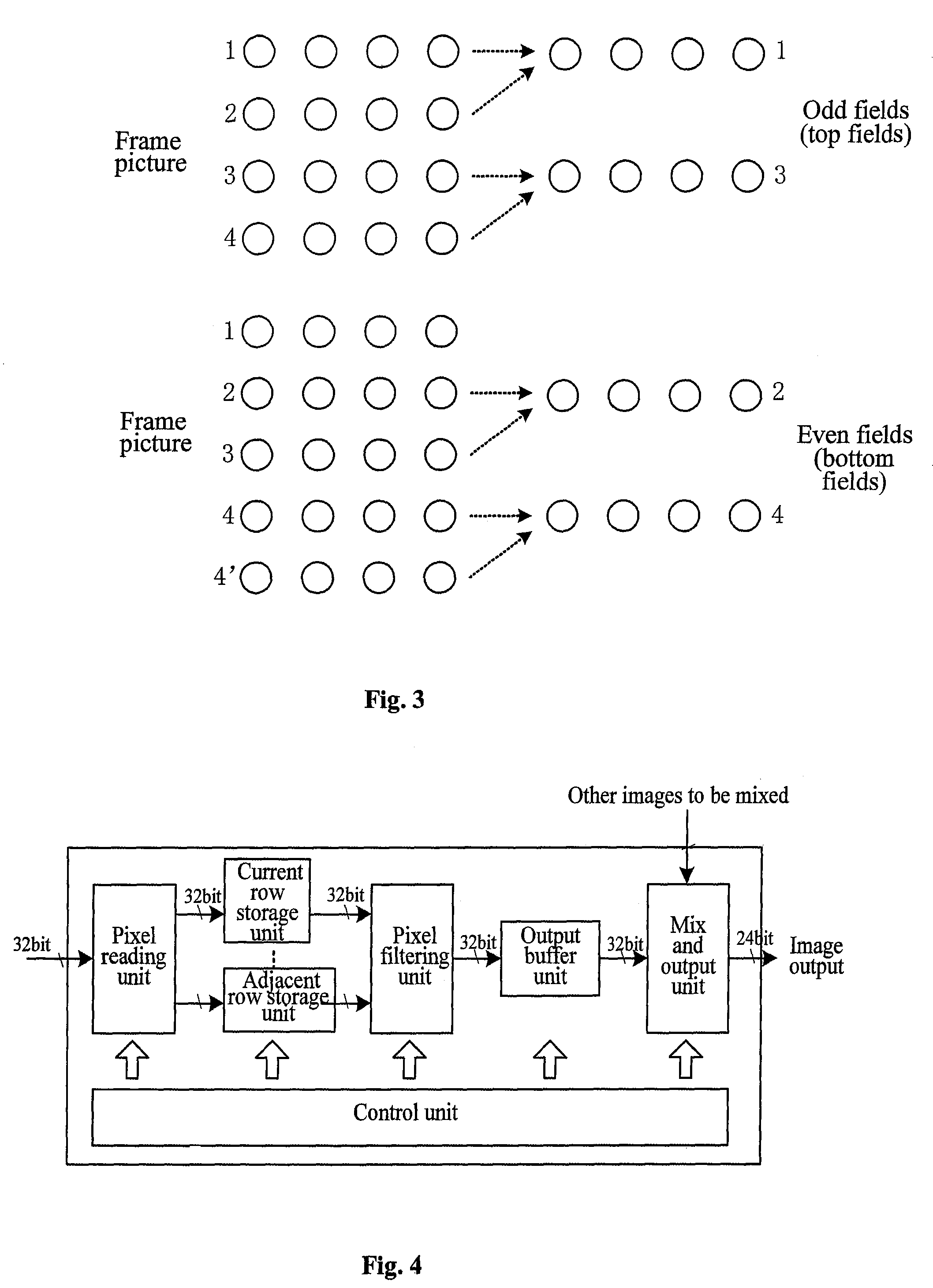
[0036]A device for image filtering is provided in the invention. Referring to FIG. 4, a structural diagram of the device according to the present embodiment is illustrated. The device includes a pixel reading unit, a current row storage unit, an adjacent row storage unit, a pixel filtering unit, and a control unit. Alternatively, the device further includes an output buffer unit and a mix and output unit. Functions of respective units will be described in details hereinafter.

[0037]The pixel reading unit, functioning as an interface through which the device is connected to the outside, is adapted to read, from a memory, image data of a current row to be processed and at least one adjacent row, and to store the data into corresponding storage units. The read image data can include totally 32-bit information, including 24-bit of brightness and colors, and 8-bit of transparencies of respective pixels.

[0038]The current row storage unit and the adjacent row storage unit are adapted respec...

second embodiment

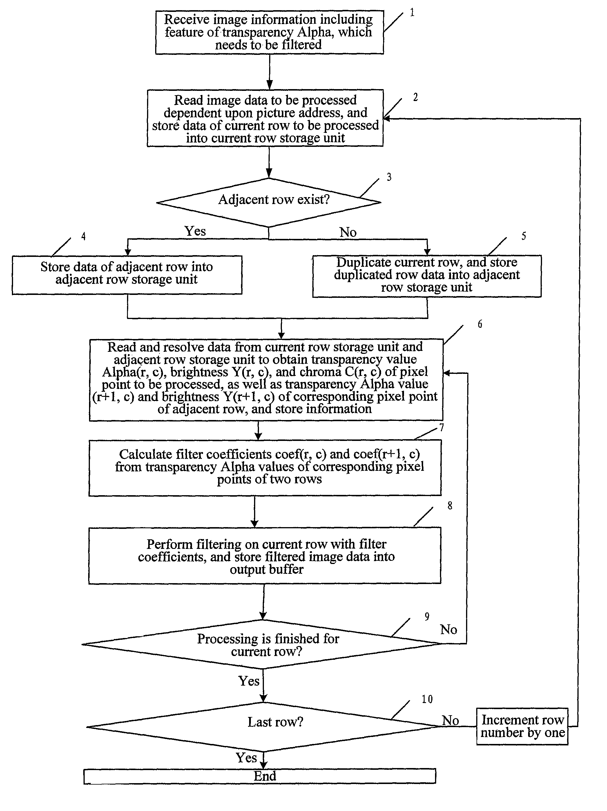
[0050]As shown in FIG. 6, a method for image filtering is provided in the invention, which includes the following blocks.

[0051]In the block 1, image information including the feature of a transparency Alpha is received, which needs to be filtered.

[0052]As filtering is required to be performed on an image, the control unit receives information on the image, where the image includes an image used as an OSD interface of a television, or as a television background, etc. The information on the image includes an address where a picture is stored, a width and a height of the picture, etc.

[0053]Pixel data including the feature of an Alpha can be of the following structure:

[0054]

[0055]In the block 2, upon receipt of the image information, the control unit notifies of the pixel reading unit, and the pixel reading unit reads the image data to be processed according to the picture address, and stores data of the current row to be processed into the current row storage unit.

[0056]In the block 3,...


PUM


Abstract

The invention discloses a method and device for image filtering in the field of communication technologies, the method including: acquiring image data of a pixel dot of a current row to be filtered and a corresponding pixel dot of at least one adjacent row; obtaining contrast information containing a transparency value, of the pixel dot of the current row and the pixel dot of the adjacent row respectively by resolving the image data of the pixel dot of the current row and the pixel dot of the adjacent row; generating a filter coefficient according to the transparency value of the pixel dot of the current row and the transparency value of the corresponding pixel dot of the adjacent row; and performing filtering on the pixel dot of the current row with the filter coefficient. The embodiments of the invention effectively avoid image flickering due to a difference between contrasts by adopting the method of at-least-two-row vertical filtering, and by generating the filter coefficients according to the transparencies in filtering.

Description

[0001]This application claims a priority from the Chinese Patent Application No. 200710063866.7, filed with the Chinese Patent Office on Feb. 13, 2007, entitled “METHOD AND DEVICE FOR INTERLACED DISPLAY ANTI-FLICKERING”, contents of which are incorporated herein by reference in its entirety.FIELD OF THE INVENTION[0002]The present invention relates to the field of communication technologies and in particular to a method and device for image filtering.BACKGROUND OF THE INVENTION[0003]Currently, most televisions employ interlaced display technique for displaying images. The interlaced display can greatly reduce the bandwidth used for transmission of signals. However, when an image edited on a computer is to be displayed in an interlaced way on a television, quality of the image tends to be degraded due to a flicker feeling with respect to the image. This results from differences between display principles of the television and the computer, where the progressive display is used for the...

Claims


Application Information

Patent Timeline
Patent Type & Authority Patents(United States)
IPC IPC(8): G06K9/40
CPCH04N7/012H04N7/0132
Inventor BAI, MENGLI, MENGLIN, HANSUN, XINGGUO
Owner HUAWEI TECH CO LTD
Learn More