Fuel cell system for promptly increasing temperature of fuel cell stack during start up operation of the fuel cell system and method of managing the fuel cell system

a fuel cell and stack technology, applied in the field of fuel cell systems, can solve the problems of not having a high voltage for practical use of electric power generated by a unit fuel cell, a long time to get back up to the normal operating temperature inside the stack, and the temperature of the secondary cooling water is generally not sufficient for the secondary cooling water

Inactive Publication Date: 2013-08-20
SAMSUNG ELECTRONICS CO LTD
View PDF9 Cites 3 Cited by
  • Summary
  • Abstract
  • Description
  • Claims
  • Application Information

AI Technical Summary

Benefits of technology

[0011]Aspects of the present invention provide a fuel cell system that promptly increases the temperature of a fuel cell stack during a start up operation of the fuel cell system and a method of managing the fuel cell system.
[0017]According to another embodiment of the present invention, there is provided a method of managing a fuel cell system, the method comprising: providing a stack in which cooling separators are formed between cells in the stack, wherein each cooling separator is formed of a metal thin plate having a first flow path and a second flow path formed in a complementary pattern on first and second opposing surfaces, respectively, of the metal thin plate; rapidly raising the temperature of the stack during a start up operation of the fuel cell system by passing discharge gas of a process burner through the first flow path formed on the first surface of the cooling separators and passing heated cooling water, heated by heat exchange with discharge gas of a process burner, through the second flow paths formed on the second surface of the cooling separators; and stopping the passing of the discharge gas through the first flow path formed on the first surface of the cooling separators and the passing of the heated cooling water through the second flow path formed on the second surfaces of the cooling separators when the temperature of the stack reaches a predetermined temperature.
[0018]According to another aspect of the present invention, there is provided a method of managing a fuel cell system, the method comprising: providing a stack in which cooling separators are formed between cells in the stack, wherein each cooling separator is formed of a metal thin plate having a first flow path and a second flow path formed in a complementary pattern on first and second opposing surfaces, respectively, of the metal thin plate and wherein the first surface of the metal thin plate includes a catalyst coated thereon that catalyzes combustion of hydrogen; rapidly raising the temperature of the stack during a start up operation of the fuel cell system by passing hydrogen through the first flow path on the first surface of the cooling separators, whereby the hydrogen combusts to generate heat and by passing heated cooling water, heated by heat exchange with discharge gas of a process burner, through the second flow path formed on a second surface of the cooling separators; and stopping the passing of the hydrogen through the first flow path on the first surface of the cooling separators and the passing of the heated cooling water through the second flow path formed on a second surface of the cooling separators when the temperature of the stack reaches a predetermined temperature.

Problems solved by technology

However, the electricity generated by a unit fuel cell 10 does not have a high enough voltage for practical use.
However, the temperature of the secondary cooling water was generally not sufficient for the secondary cooling water to be very useful as hot water.
For example, a stack may have a normal operating temperature of about 120° C. However, if a stack has been idle and has cooled to room temperature, it takes a long time to get back up to the normal operating temperature inside the stack 100.
However, at the start of the operation of the fuel cell system, such as when the stack is at or near the room temperature, it may take almost an hour until the temperature of the stack 100 reaches a temperature at which the fuel cell system is running properly, such as, for example, 120° C. Typically, the start up of the fuel processing unit 200 is much faster, and the fuel processing unit is able to supply hydrogen much sooner than the stack 100 is able to use the hydrogen efficiently, since, the fuel cell system cannot operate efficiently until the temperature of the stack 100 reaches the predetermined temperature.
Thus, a large delay occurs while waiting for the temperature of the stack 100 to reach the predetermined temperature.

Method used


Image

  • Fuel cell system for promptly increasing temperature of fuel cell stack during start up operation of the fuel cell system and method of managing the fuel cell system
  • Fuel cell system for promptly increasing temperature of fuel cell stack during start up operation of the fuel cell system and method of managing the fuel cell system
  • Fuel cell system for promptly increasing temperature of fuel cell stack during start up operation of the fuel cell system and method of managing the fuel cell system

Examples


Embodiment Construction

[0032]Reference will now be made in detail to the present embodiments of the present invention, examples of which are illustrated in the accompanying drawings, wherein like reference numerals refer to the like elements throughout. The embodiments are described below in order to explain the present invention by referring to the figures.

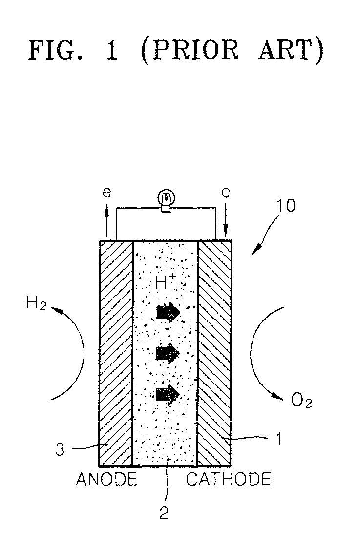
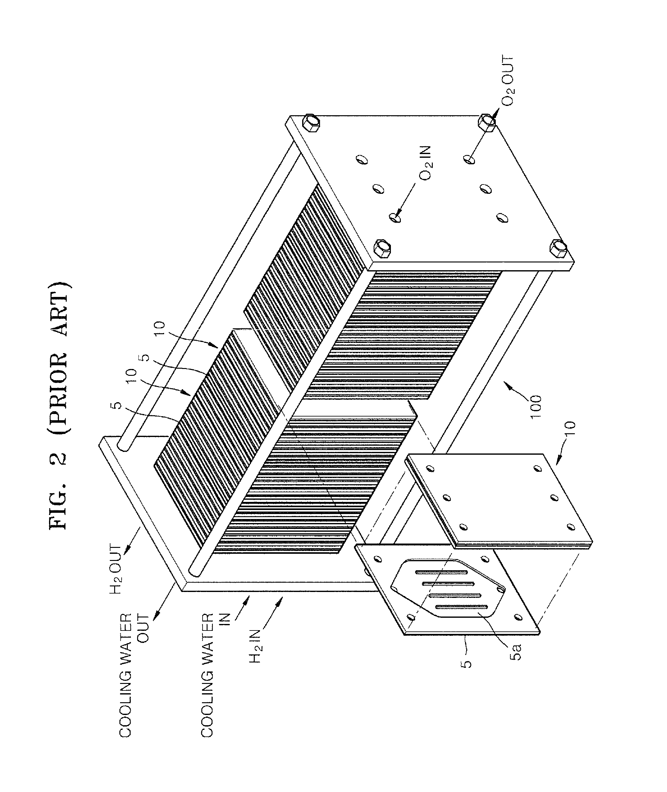
[0033]FIG. 5 is a block diagram of a fuel cell system according to an embodiment of the present invention. In the fuel cell system, hydrogen is generated in a fuel processing unit 200 and is supplied to a stack 100, and in the stack 100, the hydrogen, which is supplied from the fuel processing unit 200, is used to generate electricity in the same manner as the conventional art.

[0034]Since the fuel processing unit 200, according the present embodiment, includes elements and connection structures that are similar to those of the fuel processing unit 200 illustrated in FIG. 4, a description thereof will be omitted.

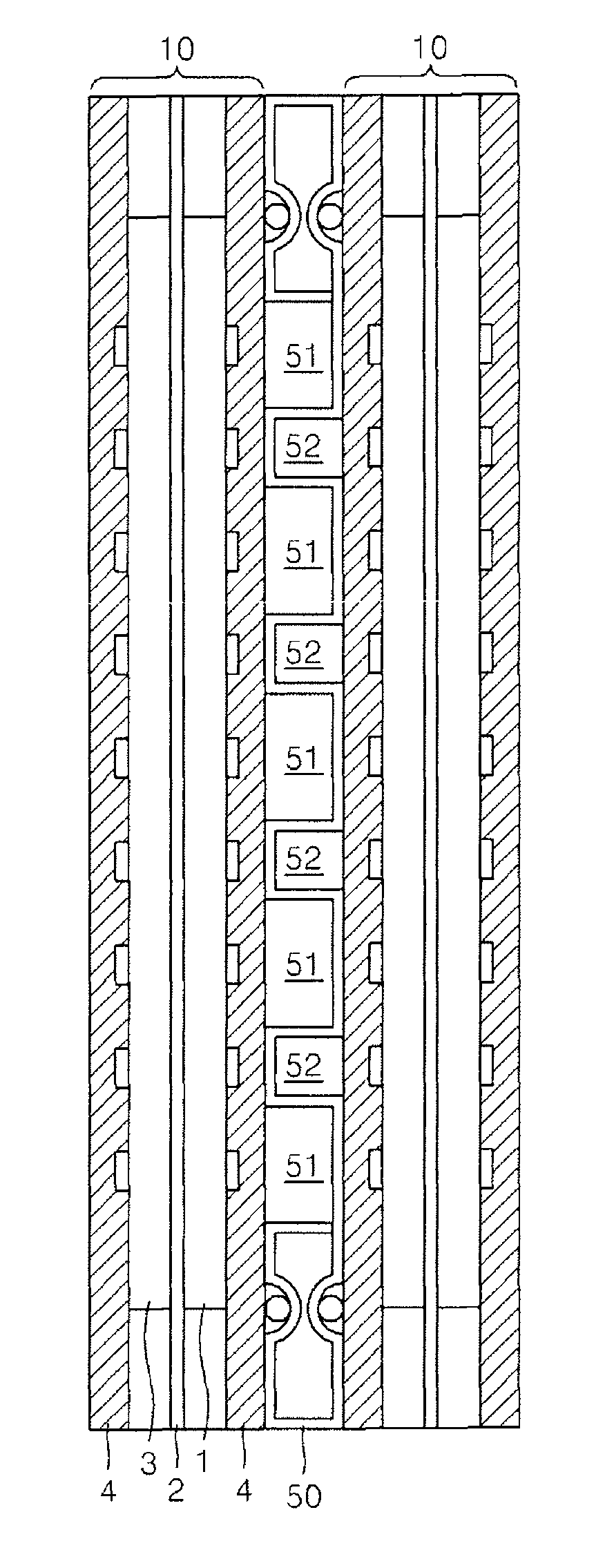
[0035]In addition, the unit cells 10 incl...


PUM

PropertyMeasurementUnit
operating temperatureaaaaaaaaaa
temperatureaaaaaaaaaa

Abstract

A fuel cell system a includes a cooling water temperature raising unit that raises the temperature of a fuel cell stack by passing discharge gas of a process burner or hydrogen gas of a fuel processing unit and cooling water that is heated by the discharge gas of the process burner through flow paths formed on opposing surfaces of cooling separators formed of a metal and installed between a plurality of cells in the stack. Thus in the fuel cell system, when the temperature of the stack needs to be rapidly raised, for example, during a start up operation of the fuel cell system, the temperature of the stack can be rapidly raised using discharge gas at a high temperature or combustion heat of hydrogen gas, and heated cooling water, and thereby, significantly reducing the time required for the fuel cell system to be in regular operation.

Description

CROSS-REFERENCE TO RELATED APPLICATION[0001]This application claims the benefit of Korean Application No. 2007-7238, filed Jan. 23, 2007 in the Korean Intellectual Property Office, the disclosure of which is incorporated herein by reference.BACKGROUND OF THE INVENTION[0002]1. Field of the Invention[0003]Aspects of the present invention relate to a fuel cell system, and more particularly, to a fuel cell system that promptly increases the temperature of a fuel cell stack during a start up operation of the fuel cell system and a method of managing the fuel cell system.[0004]2. Description of the Related Art[0005]Conventionally, a fuel cell is an apparatus that directly converts chemical energy of a fuel into electric energy through a chemical reaction. In particular, a fuel cell is used as a power generator and generates electricity as long as fuel is supplied to the fuel cell. FIG. 1 illustrates the energy conversion structure of a unit cell 10 of a conventional fuel cell. As illustra...

Claims


Application Information

Patent Timeline
Patent Type & Authority Patents(United States)
IPC IPC(8): H01M8/04H01M8/06
CPCH01M8/0267H01M8/04022H01M8/04029H01M8/0612Y02E60/50H01M8/0258H01M8/04223H01M8/04225H01M8/04302H01M8/02H01M8/04
Inventor OH, DUK-JINLEE, HYUN-CHULSONG, TAE-WONKIM, DONG-KWANWANG, YONG
Owner SAMSUNG ELECTRONICS CO LTD
Why Eureka
Try Eureka