
Fuel cell system

a fuel cell and system technology, applied in the field of fuel cell systems, can solve the problems of accelerating fuel cell systems which use liquid fuel are apt to accelerate deterioration of the fuel cell, etc., and achieve the effect of increasing the temperature of the fuel cell quickly and stably

Inactive Publication Date: 2011-12-06
YAMAHA MOTOR CO LTD
View PDF8 Cites 1 Cited by
  • Summary
  • Abstract
  • Description
  • Claims
  • Application Information

AI Technical Summary

Benefits of technology

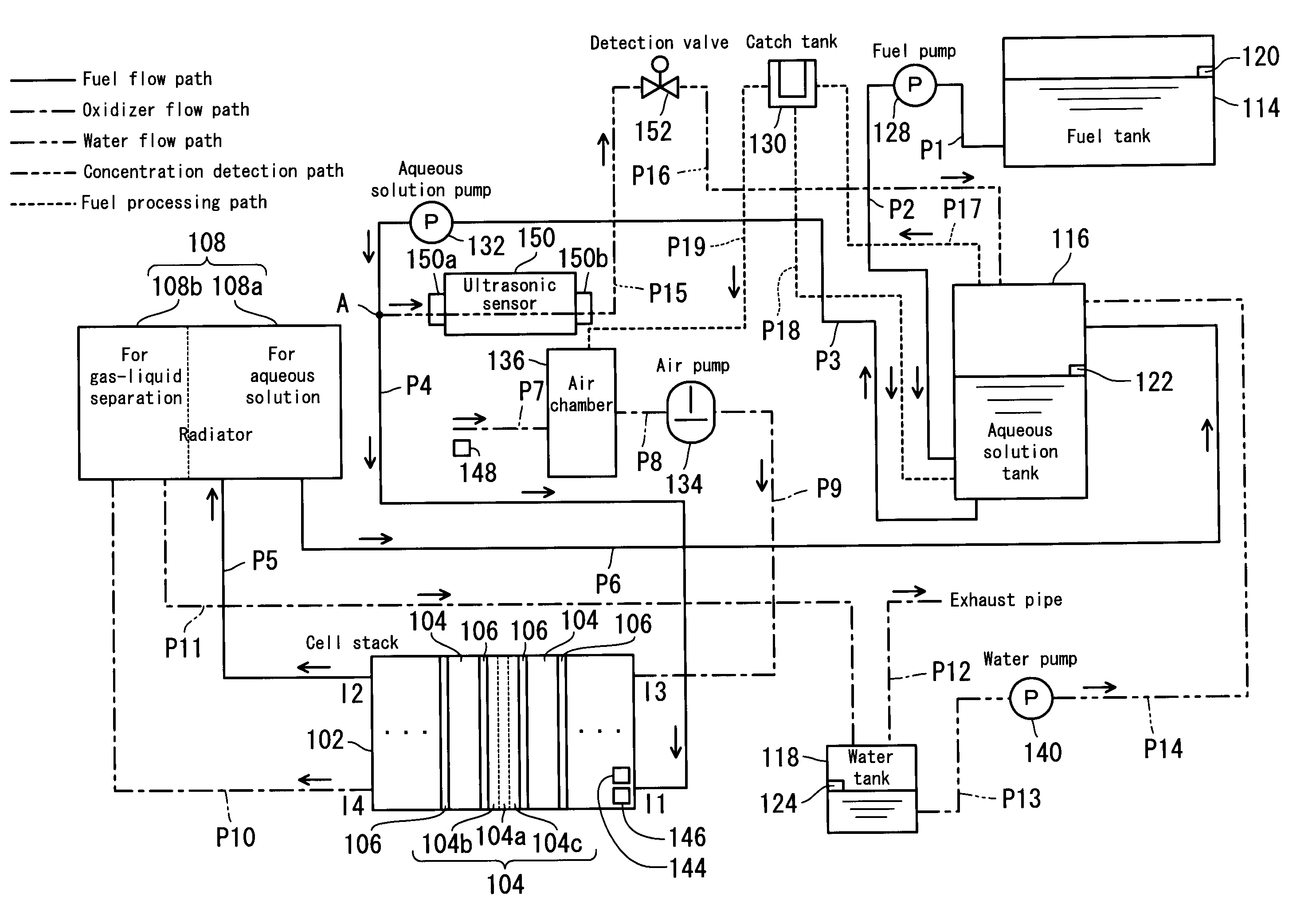
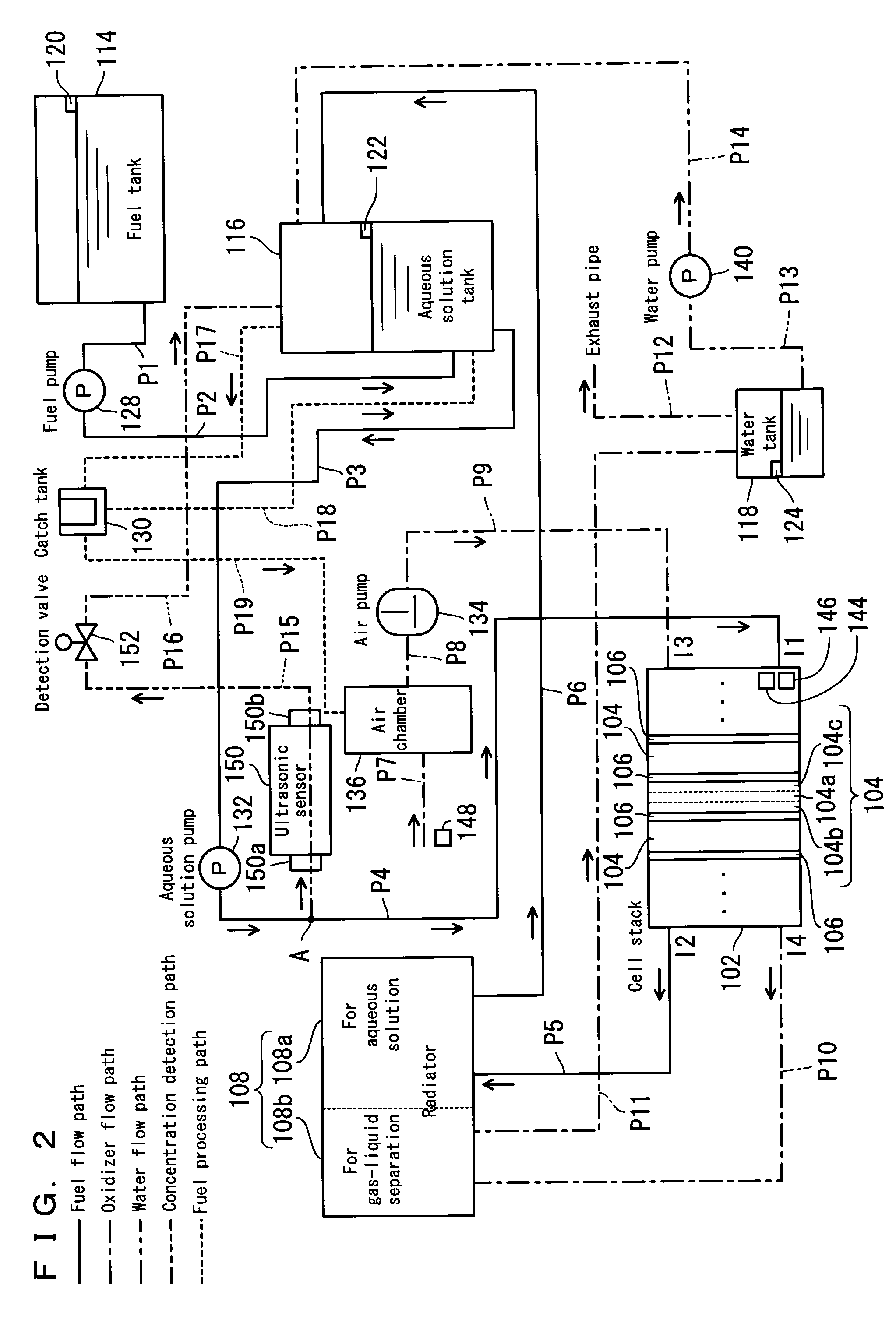
The present invention provides a fuel cell system that can quickly and stably increase the temperature of the fuel cell to a predetermined temperature regardless of the outside air temperature. The system includes a fuel cell, a temperature detection device, a temperature raising device, and a control device. The control device sets a stopping condition for the temperature raising operation based on the temperature information from the temperature detection device, and the system automatically stops the temperature raising operation at the appropriate time. This prevents excessive temperature rise and deterioration of the fuel cell. The system also includes an aqueous fuel solution supplying device that increases the concentration of the fuel solution to improve the temperature raising operation. Overall, the system provides a reliable and efficient way to increase the temperature of the fuel cell quickly and stably.

Problems solved by technology

This poses a problem of accelerated deterioration of the fuel cell.
In particular, fuel cell systems which use liquid fuel are apt to accelerated deterioration of the fuel cell since their thermal capacity is higher than those fuel cell systems which use gaseous fuel.

Method used


Image

  • Fuel cell system
  • Fuel cell system
  • Fuel cell system

Examples


Embodiment Construction

[0028]Hereinafter, preferred embodiments of the present invention will be described with reference to the drawings.

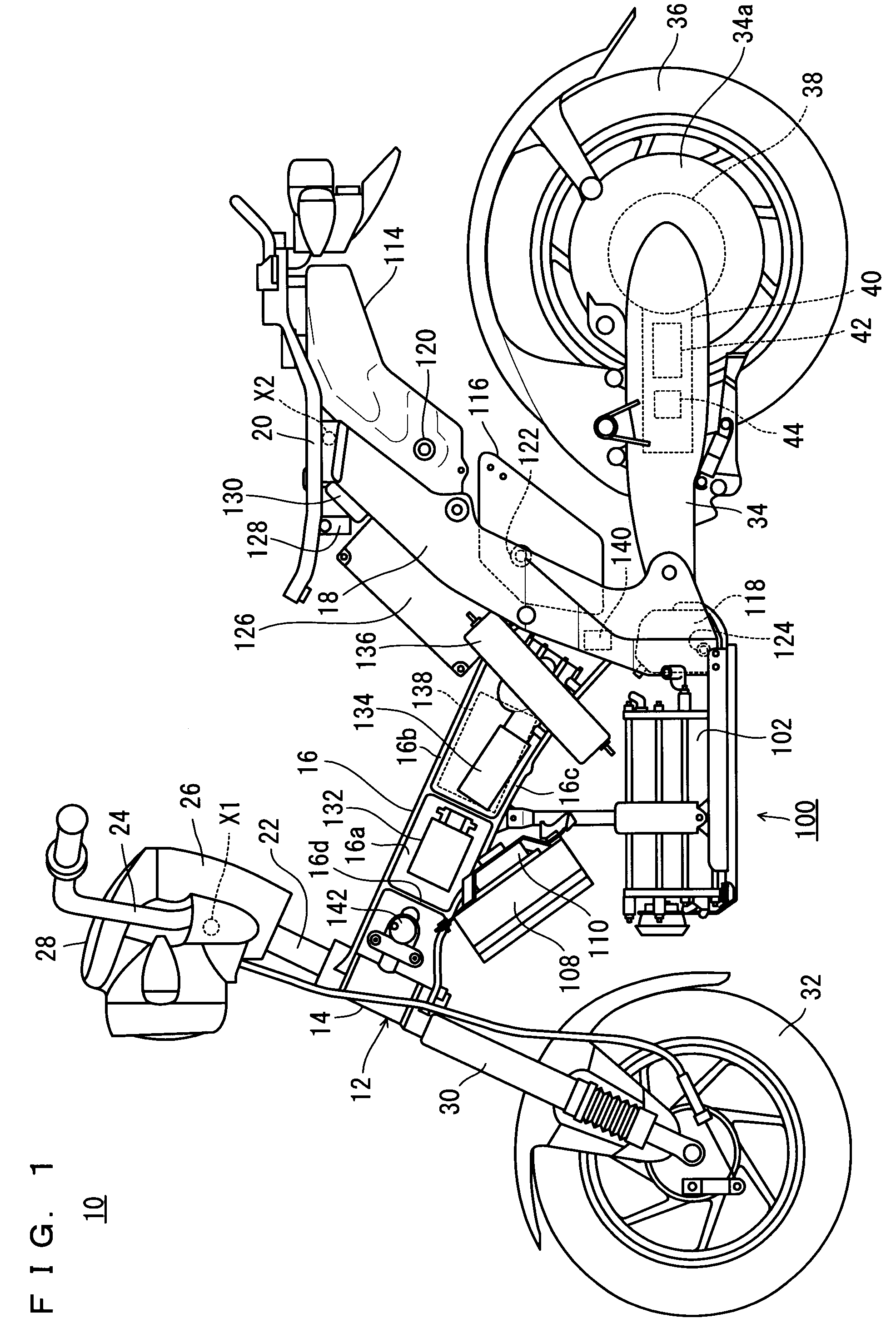
[0029]The preferred embodiments are cases in which a fuel cell system 100 is provided in a motorbike 10 as an example of transportation equipment.

[0030]The description will first cover the motorbike 10. It is noted that the terms left and right, front and rear, up and down as used in the preferred embodiments of the present invention are determined from the normal state of riding, i.e., as viewed by the driver sitting on the driver's seat of the motorbike 10, with the driver facing toward a handle 24.

[0031]Referring to FIG. 1, the motorbike 10 includes a vehicle frame 12. The vehicle frame 12 has a head pipe 14, a front frame 16 which has an I-shaped vertical section and extends in a rearward and downward direction from the head pipe 14, and a rear frame 18 which is connected with a rear end of the front frame 16 and rising in a rearward and upward direction.

[0032]The f...


PUM

PropertyMeasurementUnit
heat resistant temperatureaaaaaaaaaa
temperatureaaaaaaaaaa

Abstract

A fuel cell system includes a cell stack, a temperature sensor which detects a temperature of the cell stack, an outside air temperature sensor which detects an outside air temperature, and a CPU which controls a process in the fuel cell system. When the temperature of the cell stack is lower than a predetermined temperature, the fuel cell system performs a temperature raising operation of the cell stack by making the concentration of aqueous methanol solution in an aqueous solution tank higher than in a normal operation and by making an output of an aqueous solution pump greater than in the normal operation. The CPU sets a run time for the temperature raising operation based on a detection result from the outside air temperature sensor, a detection result from the temperature sensor, and a run time setting table which is stored in a memory. The fuel cell system is capable of raising a temperature of the fuel cell quickly and stably to the predetermined temperature.

Description

BACKGROUND OF THE INVENTION[0001]1. Field of the Invention[0002]The present invention relates to a fuel cell system, and more specifically, to a fuel cell system which performs a temperature raising operation which increases the temperature of the fuel cell.[0003]2. Description of the Related Art[0004]Generally, in fuel cell systems, it is a known fact that as the fuel cell attains a predetermined temperature, the system shifts to a normal operation where constant power generation is possible. There has been a constant demand that the system should be able to shift to normal operation quickly, and there have been a number of proposals for a fuel cell system which performs a temperature raising operation which is aimed at a quick increase in the temperature of the fuel cell. For example, there are a fuel cell system which uses a heater to perform a temperature raising operation, and a fuel cell system which performs a temperature raising operation by decreasing the amount of the aque...

Claims


Application Information

Patent Timeline
Patent Type & Authority Patents(United States)
IPC IPC(8): H01M8/04
CPCH01M8/04007H01M8/04029H01M8/04194H01M8/1011H01M2250/20Y02E60/523Y02T90/32Y02E60/50Y02T90/40
Inventor MURAMATSU, YASUYUKI
Owner YAMAHA MOTOR CO LTD
Learn More