Eureka AIR delivers breakthrough ideas for toughest innovation challenges, trusted by R&D personnel around the world.

Method for regulating the rail pressure in a common rail injection system of an internal combustion engine

a technology of injection system and internal combustion engine, which is applied in the direction of low pressure fuel injection, liquid fuel feeder, analog and hybrid computing, etc., can solve the problems of constant leakage, constant leakage, and constant leakage, and achieve the optimization of stability behavior and correction time, and reduce constant leakage. , the effect of reducing constant leakag

Active Publication Date: 2014-10-07
ROLLS ROYCE SOLUTIONS GMBH
View PDF28 Cites 2 Cited by
  • Summary
  • Abstract
  • Description
  • Claims
  • Application Information

AI Technical Summary

Benefits of technology

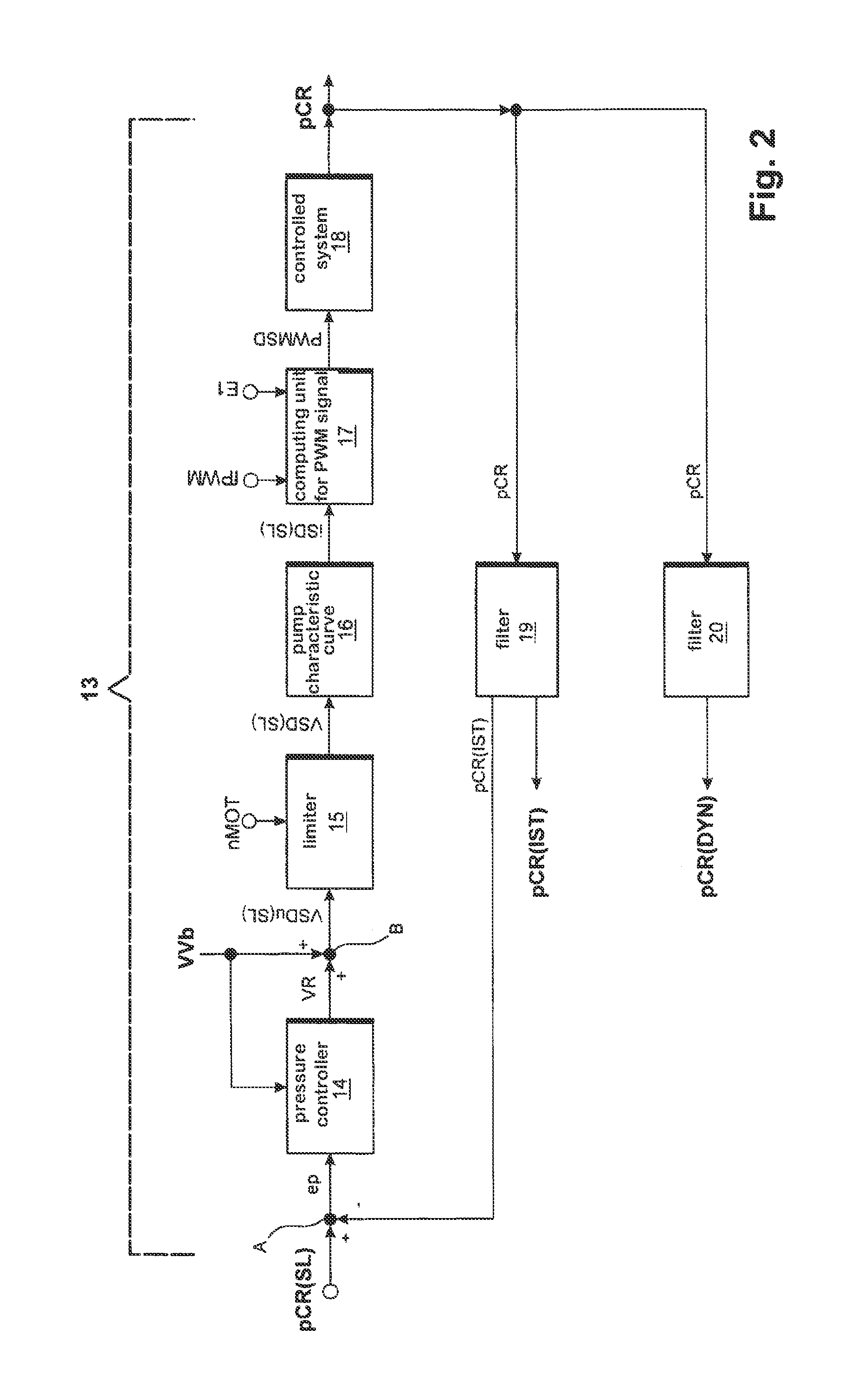
The invention aims to optimize the stability and correction time of a closed-loop rail pressure control system in an internal combustion engine. It proposes a method for controlling the rail pressure by using a suction throttle on the low-pressure side and reducing constant leakage. The system includes a normal mode and a shutdown mode for engine shutdown detection, with a zero PWM signal output when shutdown mode is set. The system also uses a static and dynamic set volume flow to compute the resultant set volume flow, which is used to control the rail pressure. Overall, the invention improves the stability and correction time of the system.

Problems solved by technology

Control leakage and constant leakage occur in a common rail system as a result of design factors.
Constant leakage is always present, i.e., even when the injector is not activated.
Since the constant leakage increases with increasing rail pressure and decreases with falling rail pressure, the pressure fluctuations in the rail are damped.
If the rail pressure rises, the injection time is shortened to produce a constant injection quantity, which leads to decreasing control leakage.
If the rail pressure drops, the injection time is correspondingly increased, which leads to increasing control leakage.
Consequently, control leakage leads to intensification of the pressure fluctuations in the rail.
However, this loss volume flow means that the high-pressure pump must be designed larger than necessary.
In addition, some of the motive energy of the high-pressure pump is converted to heat, which in turn causes heating of the fuel and reduced efficiency of the internal combustion energy.
However, a reduction of the constant leakage has the disadvantages that the stability behavior of the common rail system deteriorates and that automatic pressure control becomes more difficult.
This in turn results in a long correction time.

Method used


Image

  • Method for regulating the rail pressure in a common rail injection system of an internal combustion engine
  • Method for regulating the rail pressure in a common rail injection system of an internal combustion engine
  • Method for regulating the rail pressure in a common rail injection system of an internal combustion engine

Examples


Embodiment Construction

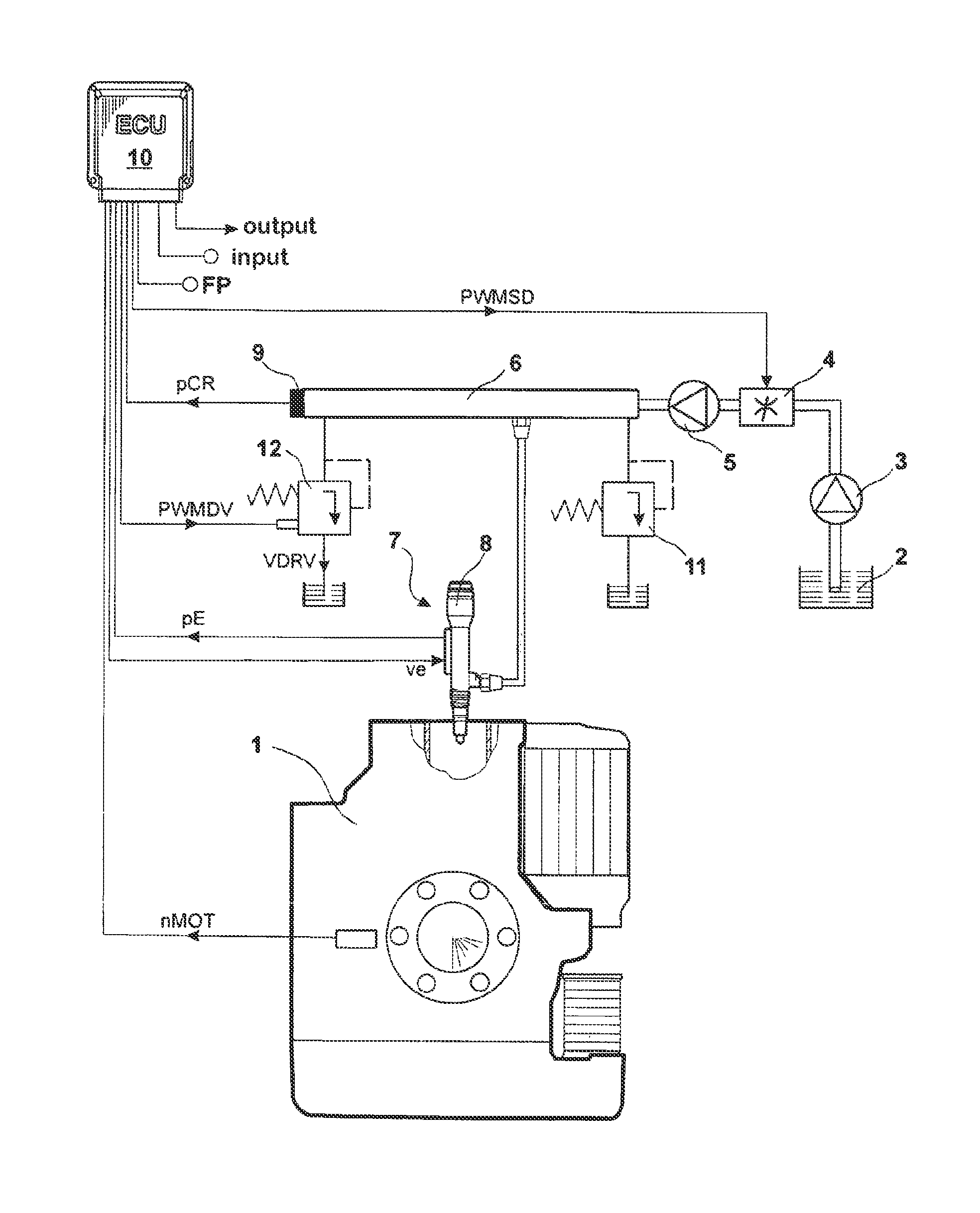
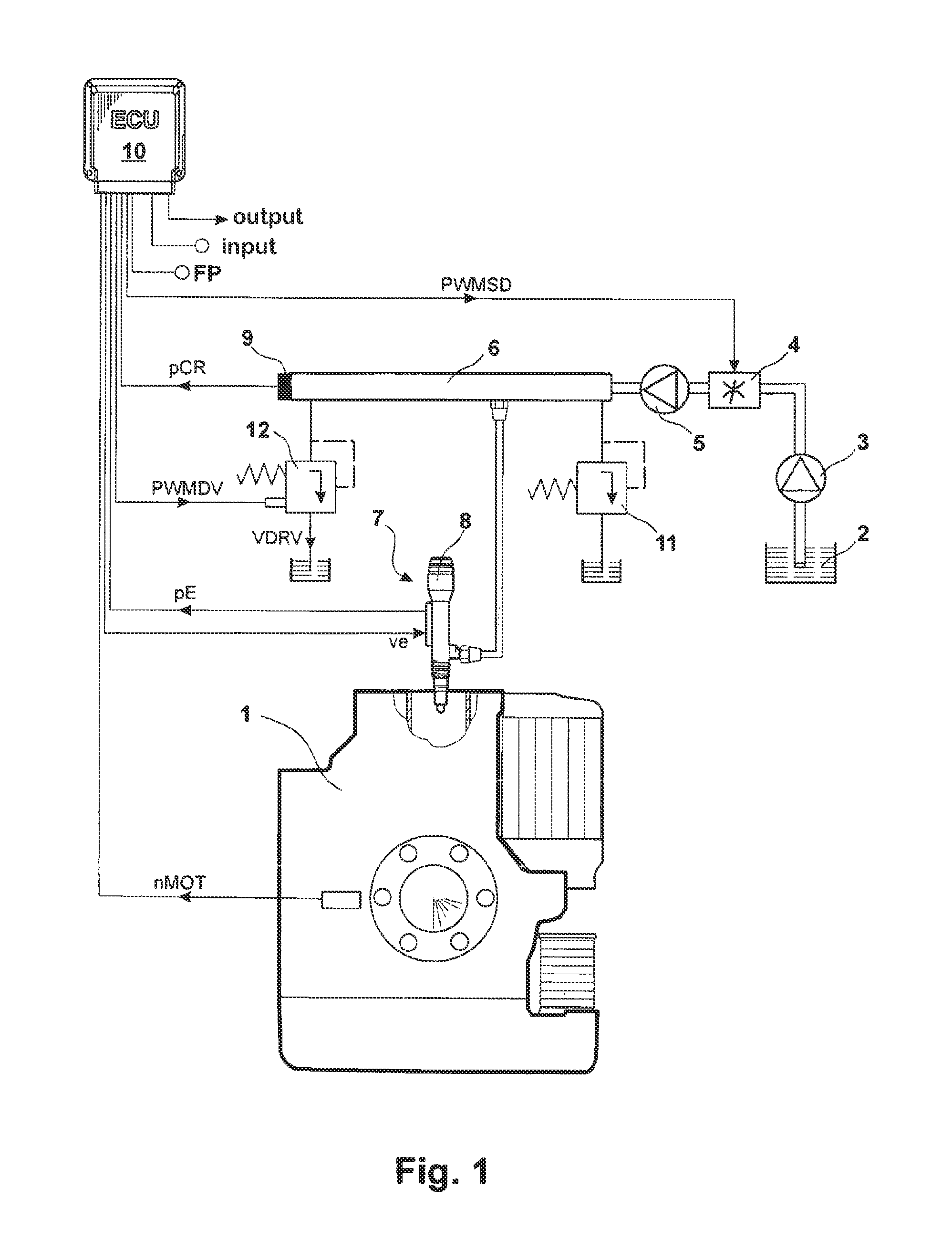
[0026]FIG. 1 shows a system diagram of an electronically controlled internal combustion engine 1 with a common rail system. The common rail system comprises the following mechanical components: a low-pressure pump 3 for pumping fuel from a fuel tank 2, a variable suction throttle 4 on the low-pressure side for controlling the fuel volume flow flowing through the lines, a high-pressure pump 5 for pumping the fuel at increased pressure, a rail 6 for storing the fuel, and injectors 7 for injecting the fuel into the combustion chambers of the internal combustion engine 1. Optionally, the common rail system can also be realized with individual accumulators, in which case an individual accumulator 8 is integrated, for example, in the injector 7 as an additional buffer volume. To protect against an impermissibly high pressure level in the rail 6, a passive pressure control valve 11 is provided, which, in its open state, redirects the fuel from the rail 6. An electrically controllable press...


PUM


Abstract

A method for open-loop and closed-loop control of an internal combustion engine (1) in which the rail pressure (pCR) is controlled via a low pressure-side suction throttle (4), as the first pressure-adjusting element in a rail pressure control loop. A rail pressure disturbance variable (VDRV) is generated to influence the rail pressure (pCR) via a high-pressure side pressure control valve (12), as the second pressure-adjusting element, by which fuel is redirected from the rail (6) into the fuel tank (2). The position of the high-pressure side pressure control valve (12) is determined by a PWM signal (PWMDV), which, when normal mode is set, is calculated as a function of the resulting target volume flow and, when protective mode is set, is temporarily set to a maximum value.

Description

[0001]The present application is a 371 of International application PCT / EP2010 / 003653, filed Jun. 17, 2010, which claims priority of DE 10 2009 031 529.2, filed Jul. 2, 2009, the priority of these applications is hereby claimed and these applications are incorporated herein by reference.BACKGROUND OF THE INVENTION[0002]The invention concerns a method for the open-loop and closed-loop control of an internal combustion engine.[0003]In an internal combustion engine with a common rail system, the quality of combustion is critically determined by the pressure level in the rail. Therefore, in order to stay within legally prescribed emission limits, the rail pressure is automatically controlled. A closed-loop rail pressure control system typically comprises a comparison point for determining a control deviation, a pressure controller for computing a control signal, the controlled system, and a software filter in the feedback path for computing the actual rail pressure. The control deviatio...

Claims


Application Information

Patent Timeline
Patent Type & Authority Patents(United States)
IPC IPC(8): F02D41/26F02D41/04F02D41/06F02D41/14F02D41/20F02D41/38F02M63/02
CPCF02D41/1401F02D41/3845F02D41/3863F02M63/025F02D41/042F02D41/062F02D2041/141F02D2041/1411F02D2041/1432F02D2041/2027F02D2200/0602F02D2250/04F02D2250/31
Inventor DOLKER, ARMIN
Owner ROLLS ROYCE SOLUTIONS GMBH
Why Eureka
Eureka Blog
Learn More