Method for starting an internal combustion engine, particularly an internal combustion engine having direct fuel injection

a technology of internal combustion engine and fuel injection, which is applied in the direction of engine starters, electrical control, tractors, etc., can solve the problems of unfavorable mixture formation, low starting reliability, and low efficiency of electrically driven fuel presupply pumps, so as to increase the starting reliability, increase the starting pressure, and cost-effective

Inactive Publication Date: 2005-07-19
ROBERT BOSCH GMBH
View PDF10 Cites 24 Cited by
  • Summary
  • Abstract
  • Description
  • Claims
  • Application Information

AI Technical Summary

Benefits of technology

[0008]In one advantageous further development of the present invention, a time elapsed since the actuation of the starter switch is monitored, and the fuel is injected into the at least one combustion chamber at the latest when the time has reached or exceeded a specifiable maximum waiting time. This ensures that even when the pressure prevailing in the high-pressure accumulator does not reach the specifiable threshold value within the predefined waiting time, a start is nevertheless attempted in order, to the greatest extent possible, to prevent a breakdown.
[0010]In a further advantageous development, an electrically actuatable presupply pump is activated for building up the injection pressure in the high-pressure accumulator. In a direct-start method without additional auxiliary drive, the internal combustion engine stands completely still until a first ignition of an air / fuel mixture. For a direct-start method without additional auxiliary drive, this development of the present invention has the advantage that the injection pressure may be generated independently of the speed of the internal combustion engine.
[0011]The buildup of the injection pressure in the high-pressure accumulator of the internal combustion engine is advantageously begun as a function of a driver-present signal. A driver-present signal here designates a signal capable of indicating whether actuation of the starter switch is to be expected in the foreseeable time. In this context, the starting point is that an actuation of the starter switch within the foreseeable time may be assumed when a driver is in the vehicle and the vehicle is switched off. In particular, the existence of a driver-present signal makes it possible to already activate the fuel presupply pump prior to an actuation of the starter switch. More time thereby remains until an actual start attempt, so that a higher rail pressure may be built up. This increases starting reliability.
[0012]In one preferred example embodiment, the driver-present signal is generated by a door contact switch. This makes it possible to generate a driver-present signal in a particularly cost-effective manner.
[0013]In a further preferred example embodiment, the driver-present signal is generated by a sensor for detecting occupancy of the driver's seat. This allows a particularly reliable judgment as to whether a driver is in the vehicle.

Problems solved by technology

However, during a start, the rail pressure is frequently not yet completely built up, which has an unfavorable effect on the mixture formation in the combustion chamber.
However, the pressure generated by the fuel presupply pump may vary strongly between individual start phases, for example, caused by immobilization times of different lengths and different ambient temperatures.
At very low temperatures, a lower battery voltage may cause an electrically driven fuel presupply pump to operate less effectively.
At high temperatures in the fuel system, e.g., after switching off a vehicle having a hot internal combustion engine, a delayed pressure buildup may take place due to a formation of steam in the fuel system.
The air / fuel mixtures thus formed in the combustion chamber may not be ignitable, which can lead to starting problems.

Method used


Image

  • Method for starting an internal combustion engine, particularly an internal combustion engine having direct fuel injection
  • Method for starting an internal combustion engine, particularly an internal combustion engine having direct fuel injection
  • Method for starting an internal combustion engine, particularly an internal combustion engine having direct fuel injection

Examples


Embodiment Construction

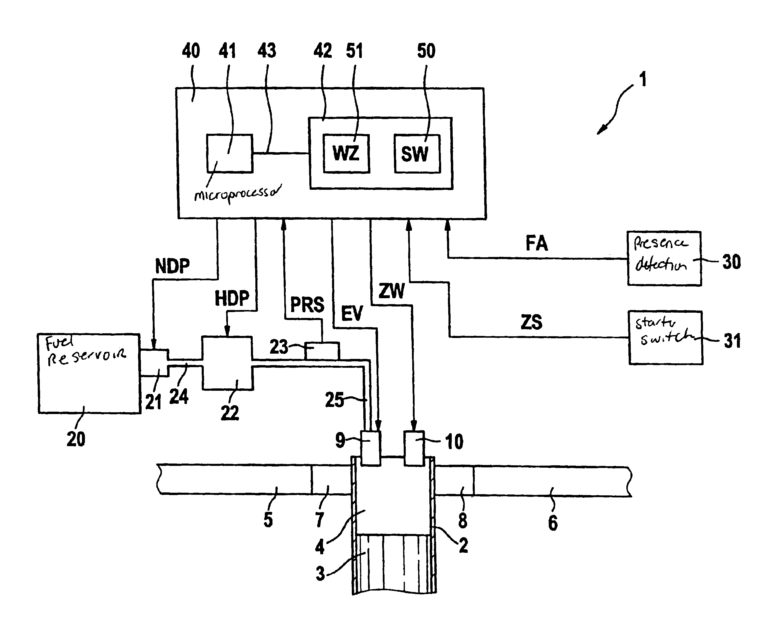
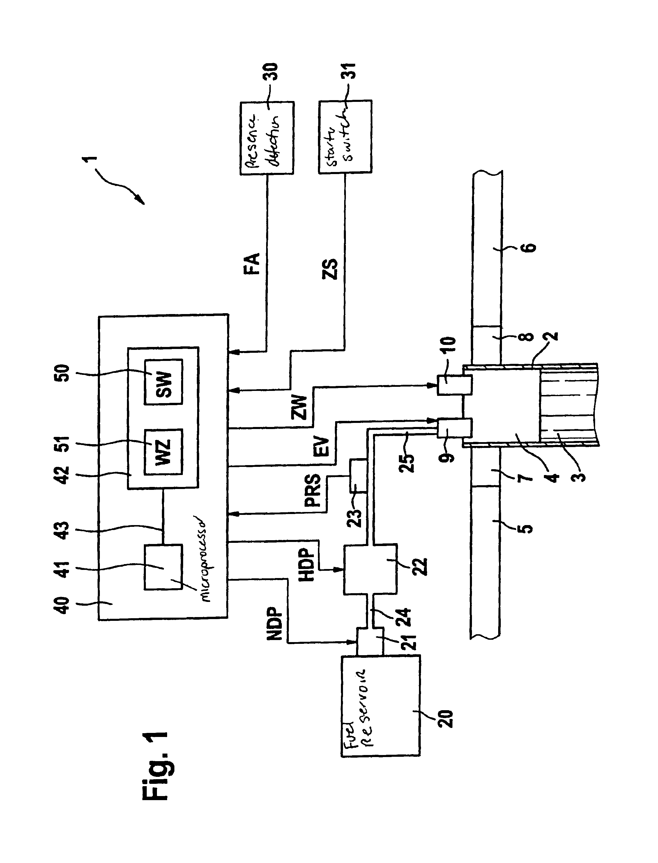
[0021]FIG. 1 shows an internal combustion engine 1 in which a piston 3 is arranged in a manner allowing it to move back and forth in a cylinder 2. Naturally, internal combustion engine 1 may also include a plurality of cylinders 2. Formed in cylinder 2 is a combustion chamber 4, to which an intake manifold 5 is connected via an intake valve 7, and an exhaust pipe 6 is connected via an exhaust valve 8. Also allocated to combustion chamber 4 are a fuel injector 9 controllable by a signal EV and a spark plug 10 controllable by a signal ZW.

[0022]Mounted at a fuel reservoir 20 is a fuel presupply pump 21 that is controllable via a signal NDP and is preferably electrically driven. It is connected via a fuel line 24 to a high-pressure pump 22 controllable via a signal HDP. A high-pressure accumulator 25 connects fuel injector 9 to high-pressure pump 22. Arranged in high-pressure accumulator 25 is a pressure sensor 23 that generates a signal PRS as a function of a pressure PR prevailing in ...


PUM


Abstract

During a start, particularly during a cold start, of an internal combustion engine without additional auxiliary drive, a precisely metered fuel mass is introduced into a combustion chamber. In the case of an internal combustion engine having direct fuel injection, a rail pressure prevailing in a high-pressure accumulator is frequently only insufficiently built up during a start, which has an unfavorable effect on the mixture formation. To improve the start performance of the internal combustion engine, the injection pressure available in the high-pressure accumulator is monitored during the start, and fuel from the high-pressure accumulator is first injected into the at least one combustion chamber when the injection pressure has reached or exceeded a specifiable threshold value. This ensures that the rail pressure is high enough, in order to inject a sufficient quantity of fuel into the combustion chamber so that an ignitable air / fuel mixture is formed.

Description

FIELD OF THE INVENTION[0001]The present invention relates to a method for starting an internal combustion engine, in which a starter switch for the internal combustion engine is actuated. After the starter switch is actuated, an injection pressure is built up in a high-pressure accumulator of the internal combustion engine. Fuel having the injection pressure available in the high-pressure accumulator is injected into at least one combustion chamber of the internal combustion engine.[0002]Furthermore, the present invention relates to a control unit for controlling and / or regulating an internal combustion engine, particularly a high-pressure injection system of the internal combustion engine, and a computer program executable on a computing element, in particular on a microprocessor.BACKGROUND INFORMATION[0003]A method as described above is conventional. In a so-called common-rail fuel injection system, a fuel presupply pump delivers fuel from a fuel reservoir into a low-pressure regi...

Claims


Application Information

Patent Timeline
Patent Type & Authority Patents(United States)
IPC IPC(8): B60K28/00B60K28/04F02D41/06F02D41/38F02D37/00F02D37/02F02B23/10F02B17/00F02D41/20F02D41/32F02D45/00F02M37/00F02M37/08F02M55/02F02N99/00
CPCB60K28/04F02D41/064F02D41/3836F02N99/006B60W2710/0616F02D37/02F02D2200/0602F02D2250/31
Inventor DENZ, HELMUTKUFFERATH, ANDREASLUDWIG, MARTIN
Owner ROBERT BOSCH GMBH
Why Eureka
Try Eureka