Method of monitoring the quality of a realtime communication

a real-time communication and quality monitoring technology, applied in the field of computer networks, can solve the problems of loss or erroneous packets that cannot be re-transmitted, difficult to efficiently measure the contribution of a packet network to streamed media quality degradation, etc., to achieve reliable judgment, reduce the bandwidth needed for quality monitoring, and simulate voice or other media transmission characteristics

Active Publication Date: 2007-06-07
ALCATEL LUCENT SAS
View PDF6 Cites 18 Cited by
  • Summary
  • Abstract
  • Description
  • Claims
  • Application Information

AI Technical Summary

Benefits of technology

[0009] Another advantage of the invention is that bandwidth needed for quality monitoring is reduced. Reference signals of a real-time comunication need not be transmitted from a transmitter through the network to a receiver, and the received packets back again to a evaluation instance. Instead, it is sufficient that the characteristics of a received packet pattern, e.g., the sequence order and the arrival time of the packets and not the content, are transmitted to the evaluation instance.
[0010] The invented method is implemented in elements of the packet network, and it can be combined with other measurement procedures, e.g., to verify data transmission. Only components common in packet networks are used. Any equipment specialised to process communication like voice or video codecs are avoided, so the method can be applied by a network operator offering packet transmission to customers, without using equipment which is specific to an application.
[0011] The invention provides an extension to pure data measurements by simulating voice or other media transmission characteristics. The invention can be implemented in a packet network by means of pure software extension; no hardware modifications are required.
[0012] Further advantages are achieved by the embodiments of the invention indicated by the dependent claims.
[0013] According to a preferred embodiment of the invention, the time of arrival of each single packet of the degraded packet stream pattern arriving one after another at the second test point and / or the sequence of arrival of the packets of the degraded packet stream pattern arriving one after another at the second test point are measured. The measured arrival times of the packets and / or the measured arrival sequence of the packets may be used as characteristics of the degraded packet stream pattern. These values may represent all used characteristics, alternatively, also other additional values and parameter of the packets may be used as characteristics of the degraded packet stream pattern.
[0014] Due to the multitude of different packet transport paths used in a packet network, the disarrangement of a packet stream pattern arriving at the second test point may be different for each transmission of the packet pattern through the network. For example, at a first transfer test, the majority of packets of the packet pattern has been transported via the same path. However, at a second transfer test, each packet of the packet pattern has been switched via a different path. In order to make a relatively reliable judgment of the transport quality of a packet network, statistics have to be compiled. Usually, it is only after a packet stream pattern has been sent a great number of times across the same network that the averaged characteristic values of the degraded packet stream pattern converge.

Problems solved by technology

Contrary to data transmission, lost or erroneous packets cannot be re-transmitted due to time constraints, but are simply omitted.
All prior art systems have considerable drawbacks which make it difficult to efficiently measure the contribution of a packet network to a streamed media quality degradation.

Method used


Image

  • Method of monitoring the quality of a realtime communication
  • Method of monitoring the quality of a realtime communication
  • Method of monitoring the quality of a realtime communication

Examples


Embodiment Construction

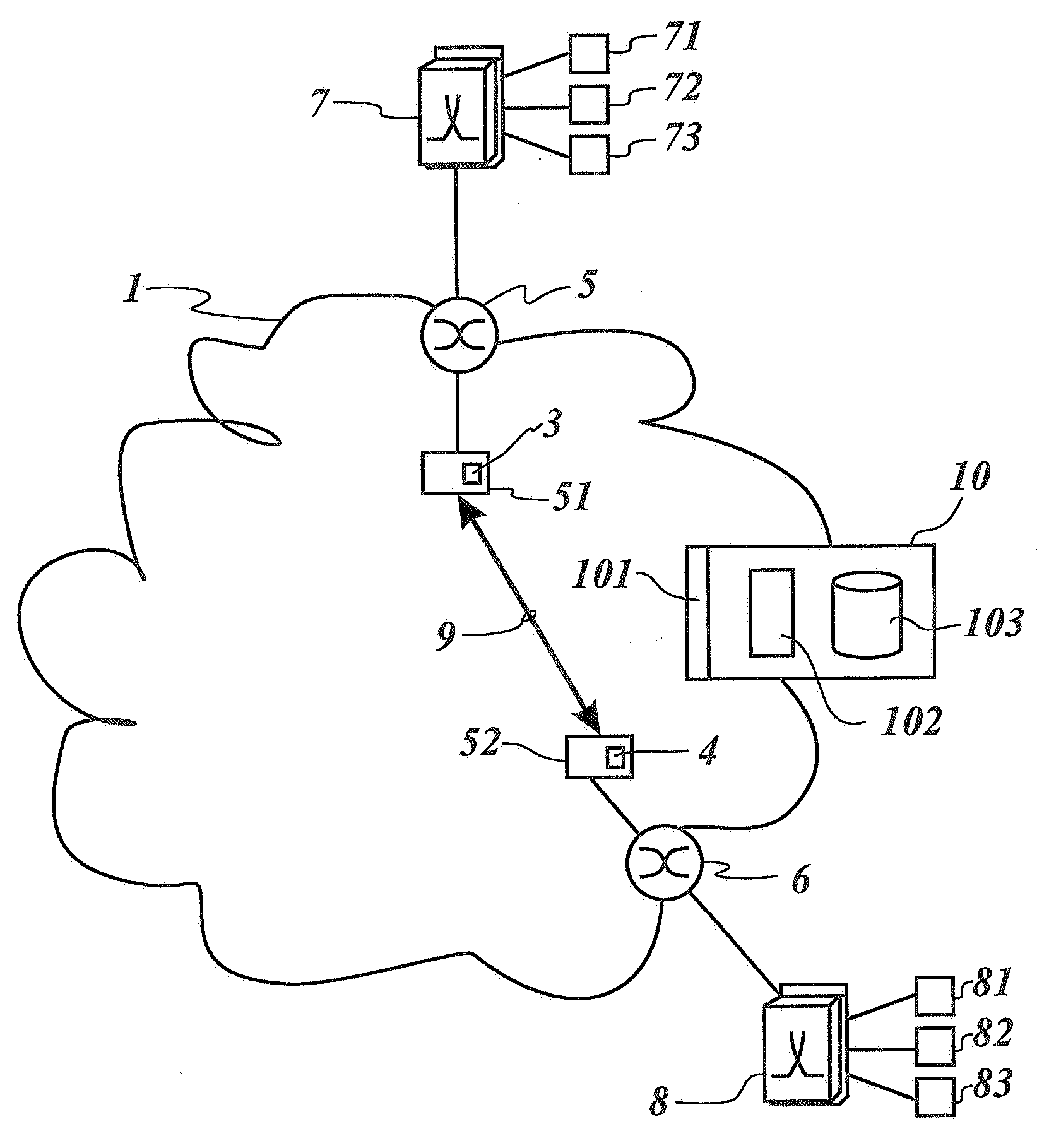
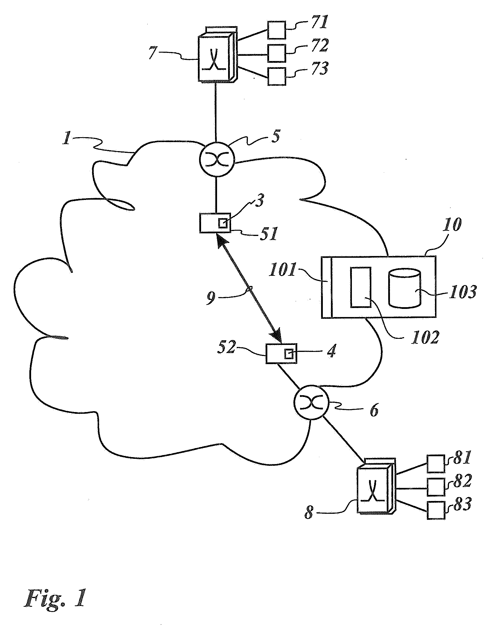
[0027]FIG. 1 shows a packet-switching network 1 operating under a packet transfer protocol such as IP, UDP, or RTP (UDP=User Datagram Protocol; RTP=Real Time Protocol). The network 1 comprises routers and switches 51, 52 for switching packets transported through the network 1, a number of test points 3, 4 located at relevant locations of the packet network 1 such as at POPs, exchanges, or switches 51, 52, and a controller 10 (POP=Point of Presence). In this description, the terms “probe” and “test point” are meant to denote the same and are used interchangeably. Each of the probes 3, 4 located at the network switches 51, 52 is connected to a gateway 5, 6 providing an interface between the packet network 1 and a local switching unit 7, 8, e.g., for switching telephony or multimedia data. The user terminals 71 to 73, 81 to 83 are connected to the local switching units 7, 8, which could also be part of a separate network.

[0028] The controller 10 comprises at least one interface module...


PUM


Abstract

The invention concerns a method, a network element and a computer program product for monitoring the quality of a real-time communication (9) in a packet network (1) comprising at least two test points (3, 4). A packet stream pattern (22) is accessed and injected at a first test point (3). After transmission of the packet stream pattern (22) through the packet network (1), a degraded packet stream pattern (23) is received at a second test point (4). Characteristics of the degraded packet stream pattern (23) are determined and compared with corresponding characteristics of the packet stream pattern (22) injected at the first test point (3). Based on the comparison, data concerning quality degradation caused by transmission over the packet network (1) is evaluated.

Description

[0001] The invention is based on a priority application EP 05 292 591.4 which is hereby incorporated by reference. BACKGROUND OF THE INVENTION [0002] In the field of computer networks, ICMP Echo, more familiar as PING, is a tool for measuring the delay of an Internet connection between a client and a target host (ICMP=Internet Control Message Protocol; PING=Packet Internet Groper). The quality of data communication is further checked by test messages resembling the real data stream, and evaluating the delay of individual messages, the transmission failures, re-transmissions and uncorrected errors. [0003] With the growing use of packet based telecommunication channels for highly delay-sensitive applications such as telephony or video conferencing, there is also a need to monitor the quality of a packetised real-time connection. Contrary to data transmission, lost or erroneous packets cannot be re-transmitted due to time constraints, but are simply omitted. Thus the degradation of the...

Claims


Application Information

Patent Timeline
Patent Type & Authority Applications(United States)
IPC IPC(8): H04J1/16
CPCH04L12/2697H04L41/5038H04L43/50H04L43/55
Inventor KLOTZ, BERNHARDACKERMANN, UWE
Owner ALCATEL LUCENT SAS
Why Eureka
Try Eureka