Rail pressure sampling before fuel injection events

a fuel injection and rail technology, applied in the direction of fuel injecting pumps, electric control, machines/engines, etc., can solve the problems of limited time available to determine, difficulty in instantaneously obtaining accurate rail pressure measurement, and fuel consumption, so as to improve the accuracy of a fuel injection even

Inactive Publication Date: 2007-03-13
CATERPILLAR INC
View PDF10 Cites 25 Cited by
  • Summary
  • Abstract
  • Description
  • Claims
  • Application Information

AI Technical Summary

Benefits of technology

[0006]In one aspect, a method of improving accuracy of a fuel injection event in a common rail fuel injection system includes a step of sensing rail pressure at least a predetermined time before a start of control signal for

Problems solved by technology

More significantly, however, is the fact that in most cases the common rail is steadily supplied with fluid from a high pressure pump, but fluid is consumed from the rail by the injectors in brief gulps.
Unfortunately, it is currently difficult to instantaneously obtain an accurate rail pressure measurement, and in the same instant generate control signals based upon that rail pressure measurement, and again in that same instant carryout the determined control signal.
Thus, one problem associated with improving delivery and timing accuracy of fuel injection events is the problem of accurately determining what the rail pressure will be at the beginning of each one of those events.
Since the processor can only do one thing at a time and because the processor is generally occupied with processing data in regular periodic intervals and controlling injector drivers during an injection event, only a limited amount of time is

Method used


Image

  • Rail pressure sampling before fuel injection events
  • Rail pressure sampling before fuel injection events
  • Rail pressure sampling before fuel injection events

Examples


Embodiment Construction

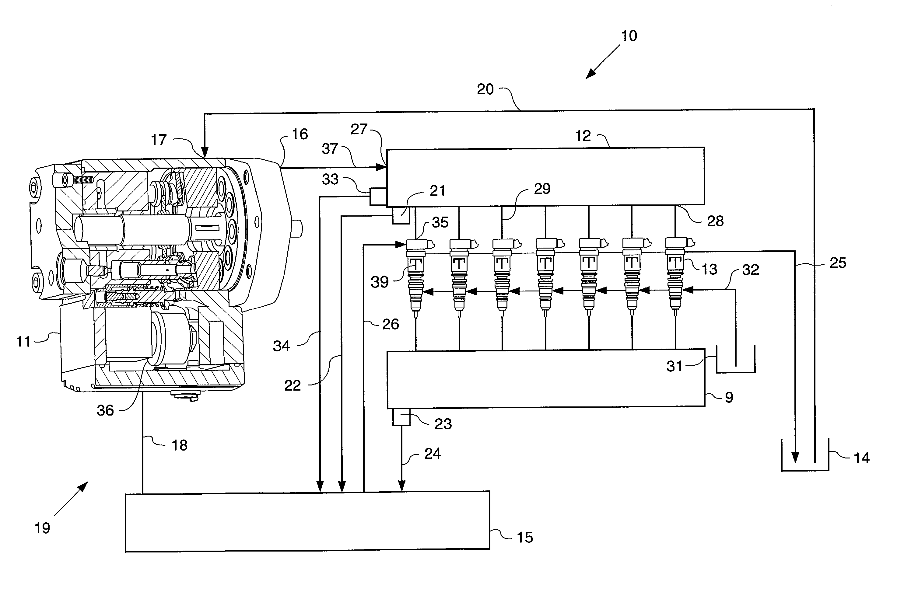
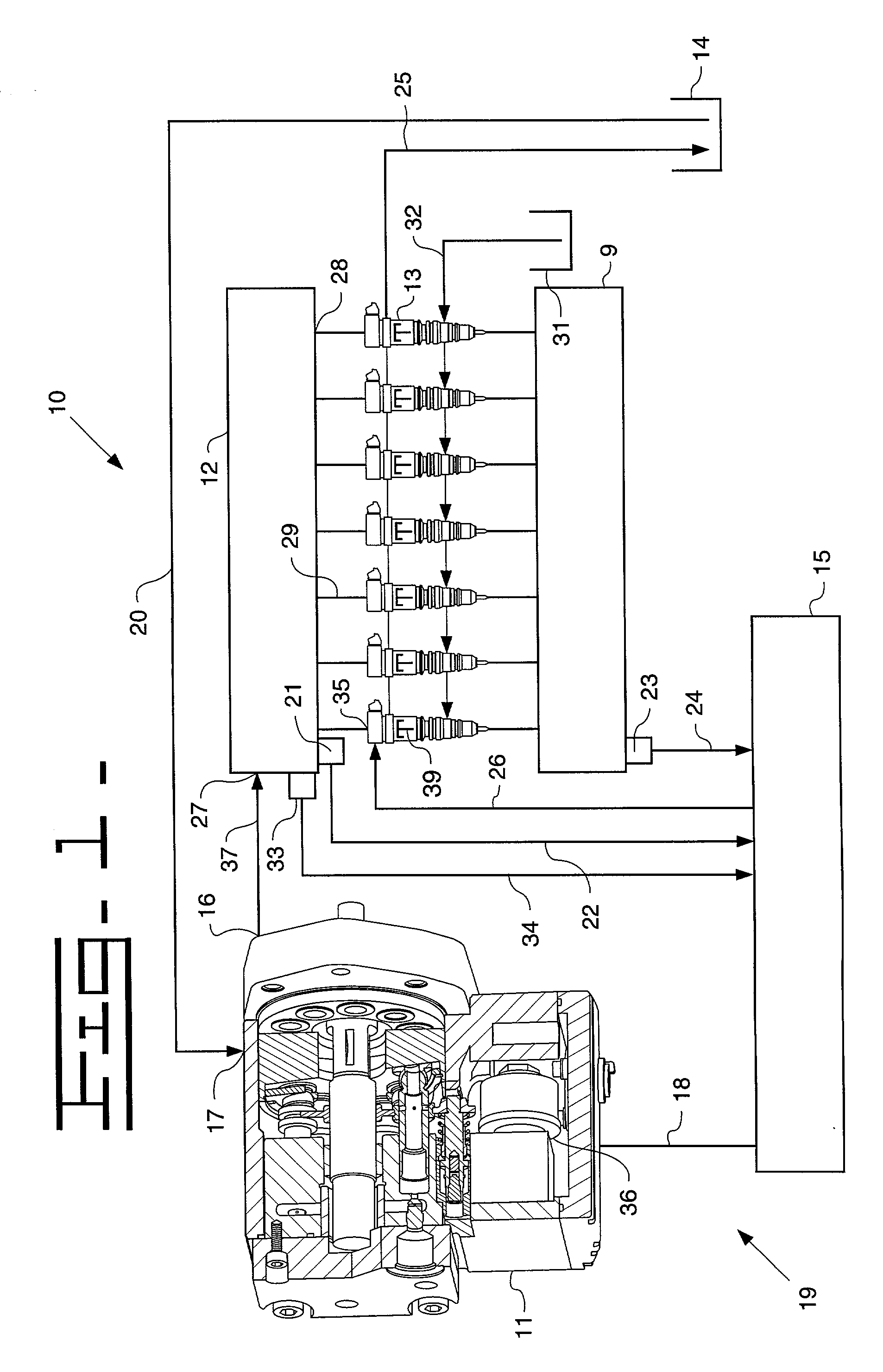
[0014]Referring to FIG. 1, an internal combustion engine 9, which is preferably a compression ignition engine, includes a common rail fuel injection system 10 that includes a pump 11, a high pressure common rail 12 and a plurality of fuel injectors 13. Pump 11 can be any suitable high pressure pump, but is preferably a fixed displacement sleeve metered variable delivery axial piston pump of the type generally described in co-owned U.S. Pat. No. 6,035,828. Those skilled in the art will appreciate that any suitable pump, such as a variable angle swash plate pump whose output is controlled via an electrical signal, could be substituted for the illustrated pump without departing from the intended scope of the present invention. In addition, fixed delivery pumps could also be utilized with the inclusion of some means to control rail pressure. For instance, in some previous common rail fuel injection systems, a fixed delivery pump is used, and a separate rail pressure control valve is uti...


PUM


Abstract

In common rail fuel injection systems, a sensed rail pressure is used to determine control signals to produce desired injection characteristics. Because rail pressure fluctuates, especially during cold start procedures, and because the rail pressure must be sensed before the injection event to be controlled, the accuracy of the timing and quantity of the injection event can be compromised if the rail pressure at the start of the injection event is different from the sensed rail pressure. In order to produce more accurate fuel injection characteristics, the rail pressure is sensed after the end of control signal for an immediately preceeding injection event but at least a predetermined time before the start of control signal for a succeeding injection event. Since the rail pressure is sensed close in time to the succeeding injection event but with adequate time to do control signal determination calculations, the accuracy in quantity and timing of the succeeding injection event can be improved because the quality of the sensed rail pressure is improved.

Description

TECHNICAL FIELD[0001]The present invention relates generally to electronically controlled common rail fuel injection systems, and more particularly to rail pressure sampling in a common rail fuel injection system.BACKGROUND[0002]Common rail fuel injection systems come in many forms. For instance, a common rail fuel injection system might maintain fuel at injection pressure levels in the common rail, and then inject at that pressure by respective fuel injectors connected to the common rail. In another example, a separate actuation fluid, such as lubricating oil, is maintained in a common rail at a medium pressure level. This actuating fluid is then supplied to individual injectors which utilize the actuation fluid to hydraulically pressurize fuel within the individual injectors to injection pressure levels. In still another example, fuel is maintained in a common rail at a medium pressure level. The individual fuel injectors connected to such a rail have the ability to inject directl...

Claims


Application Information

Patent Timeline
IPC IPC(8): F02M37/04F02D41/06F02D41/38F02D41/40F02M57/02F02M59/10F02M63/00
CPCF02D41/064F02D41/3836F02D41/401F02M57/025F02M59/105F02D2041/2058Y02T10/44F02D2250/14F02M2200/60F02D2200/0602F02D2200/0604F02D2200/0611Y02T10/40
Inventor WILSON, JEREMY J.SOLLENBERGER, ERIC E.
Owner CATERPILLAR INC
Why Eureka
Try Eureka