Fuel cell cogeneration system

a fuel cell and cogeneration system technology, applied in the direction of fuel cell applications, renewable energy sources, electric power generation of fuel cells, etc., can solve the problems of increasing the time required to raise the temperature of cooling water, the electric power consumed during the starting of the fuel cell cogeneration system is great, etc., to achieve the effect of reducing the time and raising the fuel cell temperatur

Inactive Publication Date: 2008-11-18
PANASONIC CORP
View PDF17 Cites 1 Cited by
  • Summary
  • Abstract
  • Description
  • Claims
  • Application Information

AI Technical Summary

Benefits of technology

[0010]An object of the present invention is to provide a fuel cell cogeneration system, a method of operating a fuel cell cogeneration system and a program and recording medium therefor which can raise the temperature of the fuel cell in a short period of time to reduce the time required until starting even when the difference in temperature between stored hot water and cooling water is small in the light of the afore said problems.
[0024]A fourth aspect of the present invention is the fuel cell cogeneration system of the third aspect of the present invention, wherein the aforesaid flow rate controlling means adjusts the aforesaid stored hot water flow rate adjusting means so that the aforesaid temperature of stored hot water rises to a second predetermined temperature as upper limit to reduce the flow rate of stored hot water flowing through the aforesaid stored hot water pathway and
[0036]a step of reducing the flow rate of stored hot water flowing through the aforesaid stored hot water pathway when the temperature of the aforesaid stored hot water is a first predetermined temperature or less during the starting of operation of the aforesaid fuel cell.
[0039]In accordance with the present invention, a fuel cell cogeneration system, a method of operating a fuel cell cogeneration system and a program and recording medium therefor which can raise the temperature of the fuel cell in a short period of time to reduce the time required until starting even when the difference in temperature between stored hot water and cooling water is small can be provided.

Problems solved by technology

A fuel cell cogeneration system cannot generate electricity unless the temperature of the fuel cell is raised to a predetermined temperature and thus needs to be preheated during starting.
However, the temperature raising method using a heater has a disadvantage that the electric power consumed during the starting of the fuel cell cogeneration system is great.
However, the fuel cell cogeneration system shown in FIG. 4 is disadvantageous in that it takes much time to raise the temperature of cooling water when the difference in temperature between the stored hot water and the cooling water which exchange heat with each other is small.
Further, even when only the heat recovered from exhaust gas is utilized to raise the temperature of the fuel cell as in the fuel cell cogeneration system shown in FIG. 5, the time required to start the fuel cell cannot be sufficiently reduced.
Thus, a configuration comprising one shown in FIG. 4 and one shown in FIG. 5 in combination can be proposed, but even this case is disadvantageous in that the temperature of the fuel cell cannot reach a desired operating temperature or, even if the operating temperature is reached, the time required to start the fuel cell cannot be sufficiently reduced.

Method used


Image

  • Fuel cell cogeneration system
  • Fuel cell cogeneration system
  • Fuel cell cogeneration system

Examples


embodiment 1 of implementation

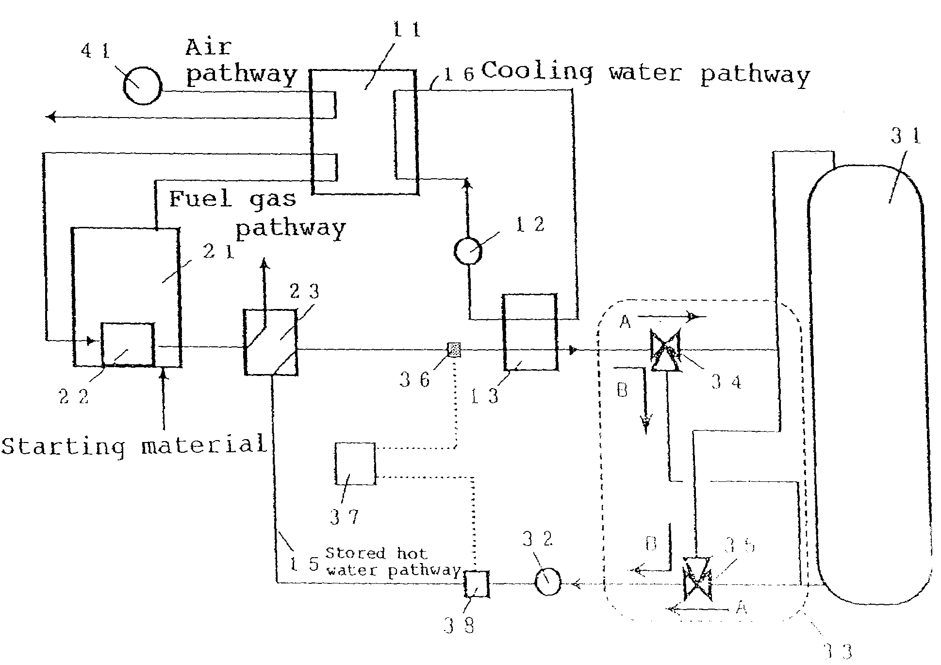
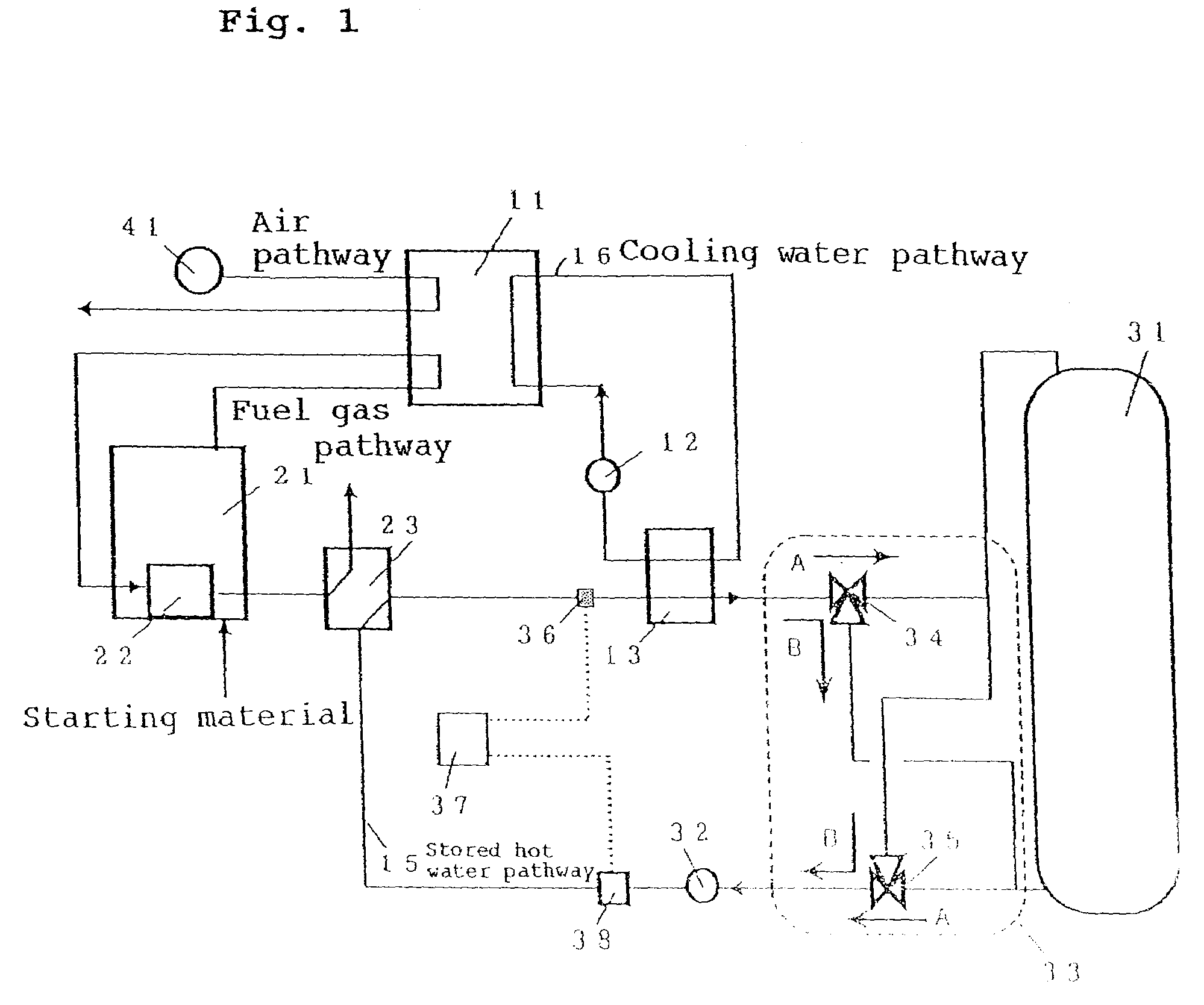
[0062]The configuration of a fuel cell cogeneration system of an embodiment 1 of implementation of the present invention is shown in FIG. 1. The fuel cell cogeneration system shown in FIG. 1 comprises a fuel cell 11 of generating electric power and heat using a fuel gas and an oxidizer gas such as air, a fuel processing means 21 of heating a starting material to produce a fuel gas and supplying the fuel gas into the fuel cell 11, a combustor 22 disposed inside the fuel processing means 21 of heating the starting material, an air supplying means 41 of supplying an oxidizer gas into the fuel cell 11, a cooling water pathway 16 of circulating cooling water of keeping the fuel cell 11 at a predetermined temperature during the operation of the fuel cell cogeneration system, a cooling water circulating pump 12 of circulating cooling water in the cooling water pathway 16, a cooling water heat exchanger 13 which is provided on the cooling water pathway 16 as an example of the first heat exc...

embodiment 2 of implementation

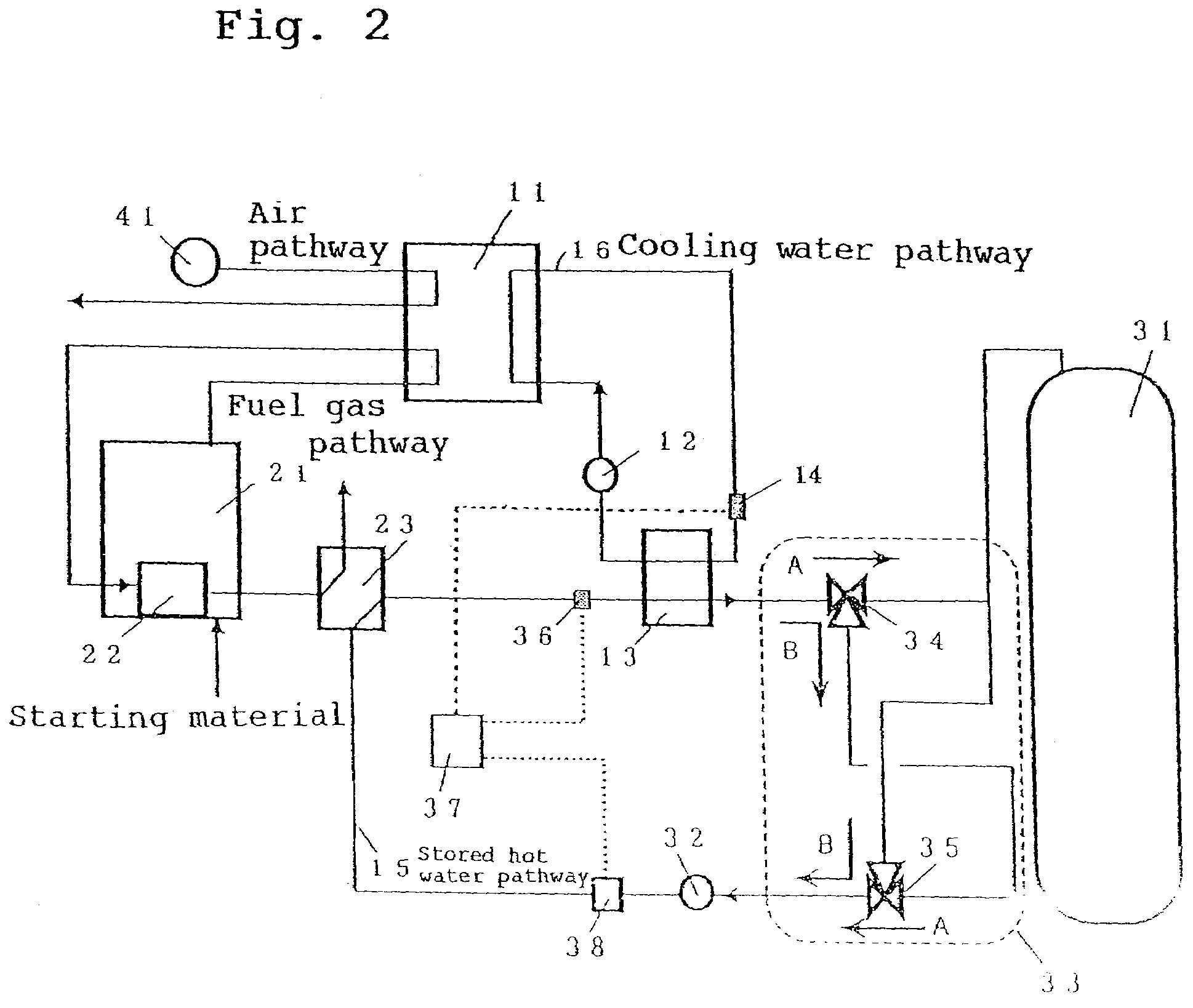
[0078]FIG. 2 is a configurational diagram illustrating a fuel cell cogeneration system in the embodiment 2 of implementation of the present invention. The same constituent elements as in Embodiment 1 of implementation are given the same reference numerals and their description will be omitted. The fuel cell cogeneration system of the present embodiment of implementation of the invention further comprises as a constituent element a cooling water temperature measuring means 14 provided upstream the cooling water heat exchanger 13 of measuring the temperature of cooling water at the inlet of the cooling heat exchanger 13. And, the flow rate controlling means 37 further has a function of adjusting the flow rate of stored hot water flowing through the stored hot water pathway 15 on the basis of the temperature of stored hot water and the temperature of cooling water by the flow rate adjusting means 38.

[0079]The operation of the fuel cell cogeneration system of the present embodiment thus...

embodiment 3 of implementation

[0085]The fuel cell cogeneration system of the present embodiment of implementation of the invention shown in FIG. 3 comprises a recovered water tank 51 connected to the exhaust gas heat exchanger 23. Inside the recovered water tank 51 is provided a water amount measuring means 52 of detecting the amount of water (water level) recovered from the exhaust gas heat exchanger 23. The water amount measuring means 52 is connected to the flow rate controlling means 37.

[0086]Next, the operation of the fuel cell cogeneration system of the present embodiment will be described.

[0087]The hot water thus heated and stored in the stored hot water tank 31 undergoes heat exchange with the cooling water in the cooling water heat exchanger 13 to heat the cooling water. At this time, the flow rate controlling means 37 controls the flow rate adjusting means 38 to adjust the flow rate of stored hot water such that the difference between the temperature of cooling water measured by the cooling water tempe...


PUM

PropertyMeasurementUnit
temperatureaaaaaaaaaa

Abstract

A fuel cell cogeneration system includes a fuel cell, a cooling water heat exchanger provided on a cooling water pathway, a stored hot water pathway through which stored hot water that exchanges heat with cooling water flows, a stored hot water tank, a stored hot water controlling device, a stored hot water temperature measuring device, a stored hot water flow rate adjusting device, a flow rate controlling device of controlling the stored hot water flow rate adjusting device and an exhaust gas heat exchanger of exchanging heat between exhaust gas from fuel processing devices and stored hot water. The flow rate controlling device controls the stored hot water adjusting device to reduce the flow rate of stored hot water flowing through the stored hot water pathway when the temperature of stored hot water is a first predetermined temperature or less during the starting of operation of the fuel cell.

Description

[0001]THIS APPLICATION IS A U.S. NATIONAL PHASE APPLICATION OF PCT INTERNATIONAL APPLICATION PCT / JP2003 / 11997.TECHNICAL FIELD[0002]The present invention relates to a method of operating a fuel cell cogeneration system which performs electricity generation and heat supply using a fuel cell and a program and recording medium therefor.BACKGROUND ART[0003]A fuel cell cogeneration system cannot generate electricity unless the temperature of the fuel cell is raised to a predetermined temperature and thus needs to be preheated during starting. In the related art fuel cell cogeneration system, a heater is used to heat cooling water by which the temperature of the fuel cell is then raised. However, the temperature raising method using a heater has a disadvantage that the electric power consumed during the starting of the fuel cell cogeneration system is great. Thus, a method has been proposed which comprises utilizing hot water stored in a stored hot water tank to raise the temperature of th...

Claims


Application Information

Patent Timeline
Patent Type & Authority Patents(United States)
IPC IPC(8): H01M8/04
CPCH01M8/04029H01M8/04223H01M8/04268H01M8/04022H01M8/0612H01M2250/405Y02E20/14Y02E60/50Y02B90/16Y02B90/10H01M8/04302H01M8/04225
Inventor TANAKA, YOSHIKAZUNAKAMURA, AKINARIOZEKI, MASATAKA
Owner PANASONIC CORP
Why Eureka
Try Eureka