Controlled-unaided surge and purge suppressors for firearm muzzles

a suppressor and unaided surge technology, applied in the field of firearms, can solve the problems of less design guidance that can lead to the integration of suppressors, less science exists to explain how current designs can be modified or replaced to provide enhanced suppressor performance, and shorten the life cycle of suppressors. the effect of noise reduction and firearm accuracy

Inactive Publication Date: 2013-09-03
FLODESIGN WIND TURBINE
View PDF18 Cites 22 Cited by
  • Summary
  • Abstract
  • Description
  • Claims
  • Application Information

AI Technical Summary

Benefits of technology

[0020]This new “CUSPS” approach attends to the blast surge effects by controlling the flow expansion into the suppressor, and attends to the flash effects by controlling inflow and outflow gas purging. The “CUSPS” rapidly reduces the pressure energy associated with a firearm muzzle blast before it exits the suppressor, thereby reducing noise and muzzle flash.
[0023]Note that the two C-I-P embodiments contain no “outside” vent holes which extend through the suppressor housing's outer wall (i.e., throughbores). Instead of ingesting ambient air through such vent holes and mixing that air with the muzzle gases, as shown in the parent application, the C-I-P embodiments have different structures and work in a different manner. They too though can control or eliminate the Mach disk.
[0024]Based upon preliminary testing, Applicants believe that their C-I-P embodiments will generate the following benefits: lower noise; hide or eliminates flash; integrate cooling and self-cleaning; and maintain firearm accuracy at longer distances.

Problems solved by technology

Existing suppression technology reduces noise and flash, but comparatively little science exists to explain how current designs can be modified or replaced to provide enhanced suppressor performance, including the useful life span of the suppressor.
Furthermore, even less design guidance exists that can lead to integration of suppressors into a firearm's barrel assembly.
Lessons learned as a result of the ongoing military and homeland security based conflicts have indicated that increased use of current suppressors, as part of everyday operations, have led to shortened life cycles of suppressors, increased maintenance (and sometimes damage) of weapons, and considerable variability in weapon accuracy.
Both of these blasts are sources of low frequency noise that carry very far distances.
The over-expanded gas results in the normal shock or Mach disk, which causes the secondary flash and a significant portion of the noise.
Gas turbine technology has yet to be applied successfully to firearm muzzle suppressors.

Method used


Image

  • Controlled-unaided surge and purge suppressors for firearm muzzles
  • Controlled-unaided surge and purge suppressors for firearm muzzles
  • Controlled-unaided surge and purge suppressors for firearm muzzles

Examples


embodiment 100

[0071]Experimental and analytical analyses of the “CUSPS” embodiment 100 indicates: the “CUSPS” can reduce the noise induced by the firearm's muzzle blast wave, reduce the radiant flash caused by the propellant gases and ingest ambient air to both cool the suppressor and purge it of residual gases, thereby increasing its useful life span.

[0072]Based on their experimental and analytical results, and the observation that the vent holes permits easier flushing of the interior volume with cleaning fluids, the Applicants believe the “CUSPS” embodiment 100 will reduce the blast wave induced noise at three feet from the muzzle exit by 20 db or more, make the gas flash visually undetectable to an observer at any distance greater than 1000 muzzle diameters, and have an indefinite useful lifetime if properly maintained.

[0073]In the embodiment 100, the entrance and lobed nozzle 116 serve to control and reduce the static pressure of the gases exiting the muzzle while the vent holes 104 first di...

embodiment 1000

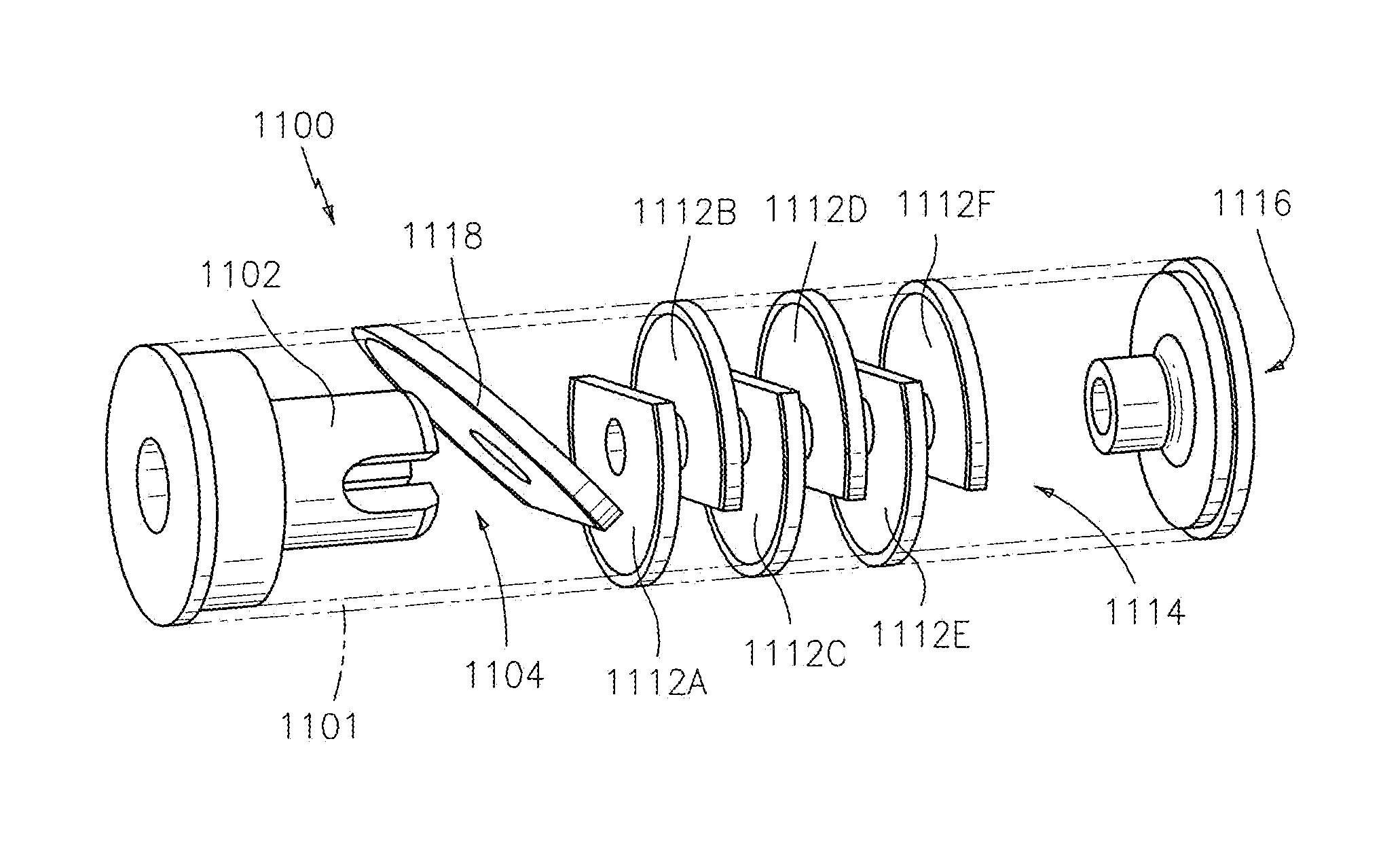
[0106]FIGS. 14 and 15 depict elements like those found in the preferred embodiment 1000, shown in FIGS. 11-13, but reference them with the prefix 1100 rather than 1000. For example, the alternating baffles are referenced as 1112A, 1112B, 1112C, 1112D, 1112E, 1112F in FIGS. 14 and 15.

[0107]Both of these blast baffle configurations create an immediate disruption in the flow while allowing the gas to travel a path besides on centerline.

[0108]Field tests of the design shown in FIG. 11 verified high levels of noise and flash suppressor, while maintaining aiming accuracy with virtually no negative impact on the loading and firing mechanisms.

[0109]As in the parent Application, the entrance divergent nozzle's exit diameter and length (in the C-I-P embodiments) are established using classic gas dynamic principals to produce isentropic, or near isentropic, expansion of the muzzle gases into the suppressor.

[0110]The exit nozzle diameter and length are established using classic gas dynamic prin...


PUM


Abstract

A Controlled Unaided Surge and Purge Suppressor for firearms uses the blast and plume characteristics inherent to the ballistic discharge process to develop a new two-step controlled surge and purge system centered around advanced mixer-ejector concepts. The blast surge noise is reduced by controlling the flow expansion, and the flash effects are reduced by controlling inflow and outflow gas purges. This is a C-I-P application. In the preferred C-I-P embodiment, the blast surge is mitigated via a slotted mixer nozzle; a first expansion chamber; a generally “wagon-wheel” shaped blast baffle with a vent hole; a series of alternating baffles, with vent holes, strategically located along the suppressor's inner wall surface; a second expansion chamber; and an exit opening. This preferred C-I-P embodiment contains no “outside” vent holes (i.e., throughbores) which extend through the suppressor's outer or longitudinal wall. Instead of ingesting ambient air through such throughbores and mixing that air with the muzzle gases, as shown in the parent application, the preferred C-I-P embodiment ingests and mixes chamber gases and contaminants with the muzzle gases while allowing fluid flow through and out the suppressor. It too though can control or eliminate the Mach disk.

Description

[0001]This is a continuation-in-part (“C-I-P”) application of U.S. Utility patent application Ser. No. 12 / 212,166, filed Sep. 17, 2008 now U.S. Pat. No. 8,322,266 (“Parent Application”), which was based upon a U.S. Provisional Patent Application, Ser. No. 60 / 994,280, filed Sep. 18, 2007.FIELD OF INVENTION[0002]The present invention deals generally with firearms. More particularly, it deals with noise and flash suppressors for firearm muzzles.BACKGROUND OF INVENTION[0003]Reducing muzzle noise and flash from military and security personnel firearms (e.g., long guns and pistols) provide a significant tactical advantage in the field. Existing suppression technology reduces noise and flash, but comparatively little science exists to explain how current designs can be modified or replaced to provide enhanced suppressor performance, including the useful life span of the suppressor. Furthermore, even less design guidance exists that can lead to integration of suppressors into a firearm's ba...

Claims


Application Information

Patent Timeline
Patent Type & Authority Patents(United States)
IPC IPC(8): F41A21/00
CPCF41A13/08F41A21/30F41A21/34
Inventor PRESZ, JR., WALTER M.WERLE, MICHAEL J.LIPKENS, BARTGAWENCKI, JASON
Owner FLODESIGN WIND TURBINE
Why Eureka
Try Eureka