Device for reducing pressure pulses in pressure sensors

a technology of pressure sensor and pressure pulse, which is applied in the direction of fluid pressure measurement, instruments, shock absorbers, etc., to achieve the effect of substantial delay and light risk of clogging

Active Publication Date: 2014-09-02
ROBERT BOSCH GMBH
View PDF12 Cites 7 Cited by
  • Summary
  • Abstract
  • Description
  • Claims
  • Application Information

AI Technical Summary

Benefits of technology

[0005]An object of the present invention is to integrate a damping insert into a channel, for example a pressure channel of a pressure sensor. This results in a simplification of the manufacture, and an improved damping of occurring pressure pulses or a reduction of pressure peaks is achieved. The use of a damping insert having at least one damping channel is capable of reducing the technical problem of limited manufacturability and the influence on the interface geometry or the connection process.
[0006]The geometric design of the damping insert considerably increases the propagation of the pressure pulse. For example, the damping channel on the damping insert may extend like a thread turn on its peripheral surface, thus making it possible to increase the length of the damping channel considerably—in this case extending in the circumferential direction. The damping insert having its at least one damping channel provided on the peripheral surface is installed in the housing of the pressure sensor in such a way that, for example, one or several damping channels extending in the shape of a spiral on the peripheral surface of the damping insert are covered, i.e., closed by the housing wall. The increased wall friction, to which a pressure pulse passing through the at least one damping channel is exposed, and occurring interferences make it no longer possible for pressure peaks, which ultimately contact the sensor element, to damage it, since the pressure energy is considerably reduced during the passage of the at least one damping channel along the peripheral surface of the damping insert. The geometric shape of the at least one damping channel may be designed in an optimal way for the manufacture of the damping insert.
[0008]The damping capacity of the damping insert described according to the present invention, for example, in the pressure channel of the housing of the damping insert integrated into the pressure sensor, is determined in particular by the length of the at least one damping channel on the peripheral surface of the damping insert. The longer the length of the damping channel extending in the circumferential direction is made, the greater is the possible damping of the pressure pulse passing through this at least one damping channel. Advantageously, the damping capacity of the damping insert described according to the present invention is advantageously influenced by several openings distributed on the periphery, resulting in a relatively slight risk of clogging caused by particles contained in, the gaseous medium. The damping insert described according to the present invention also makes it possible to cause the propagations of the pressure pulses to cross over with a mutual elimination of the pressure pulses within the damping channel, and due to the length of the at least one damping channel in the circumferential direction on the peripheral surface of the damping insert, it is possible to achieve a substantial delay of the pressure pulse.

Problems solved by technology

The increased wall friction, to which a pressure pulse passing through the at least one damping channel is exposed, and occurring interferences make it no longer possible for pressure peaks, which ultimately contact the sensor element, to damage it, since the pressure energy is considerably reduced during the passage of the at least one damping channel along the peripheral surface of the damping insert.

Method used


Image

  • Device for reducing pressure pulses in pressure sensors
  • Device for reducing pressure pulses in pressure sensors
  • Device for reducing pressure pulses in pressure sensors

Examples


Embodiment Construction

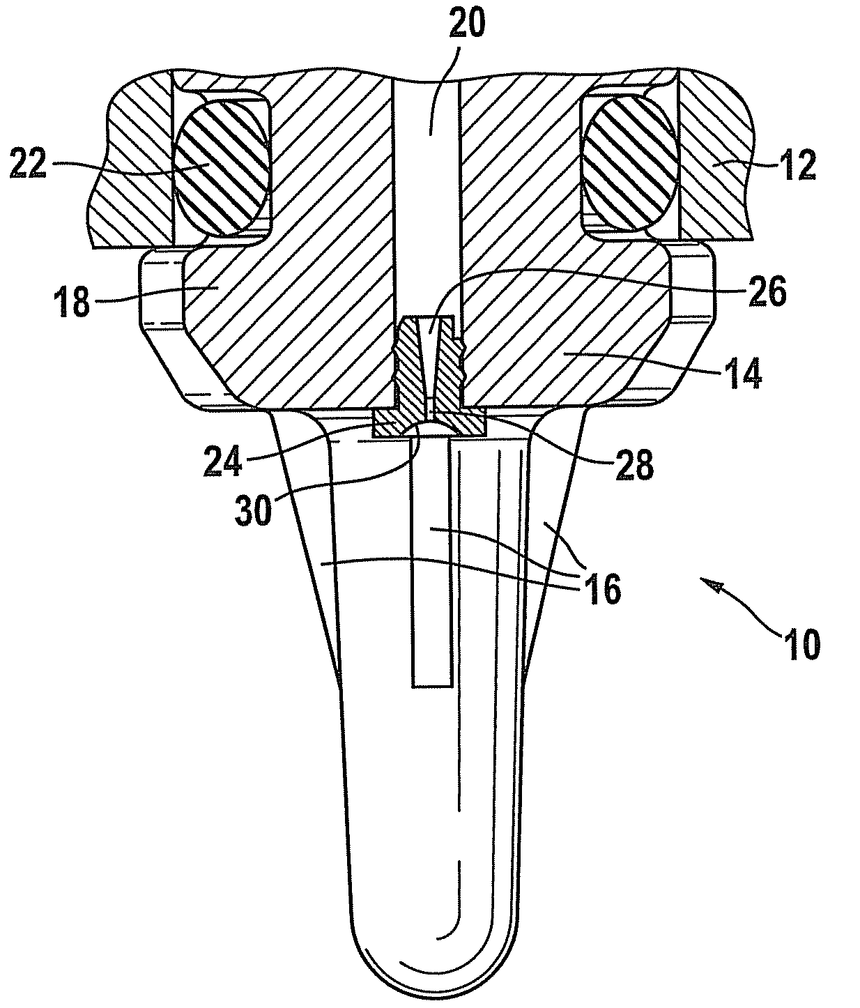
[0016]The representation according to FIG. 1 shows a sensor, in particular a pressure sensor 10, the housing 14 of which is fastened to a flange 12. The sensor, in particular designed as a pressure sensor 10, extends vertically downward on one flat side of flange 12. Pressure sensor 10 includes housing 14, through which a pressure channel 20 extends. FIG. 1 also shows that housing 12 of pressure sensor 10 is sealed relative to flange 12 with the aid of a sealing element 22. Housing 14 includes a thread which is not shown in FIG. 1, via which housing 14 of pressure sensor 10 is fastened to flange 12. During attachment of housing 14 of pressure sensor 10, the upper annular surface of a shoulder 18, which is formed on housing 14, contacts a lower flat side of flange 12 and compresses sealing element 22 which is inserted into a corresponding recess of housing 14 of pressure sensor 10. As FIG. 1 also shows, pressure channel 20, in which throttle insert 24 is formed, extends through housi...


PUM

PropertyMeasurementUnit
pressureaaaaaaaaaa
dampingaaaaaaaaaa
volumeaaaaaaaaaa

Abstract

A device for damping pressure pulses, in particular in a pressure sensor. The pressure sensor includes a housing. A damping insert, on whose peripheral surface runs a damping channel, is located in the pressure channel of the housing.

Description

BACKGROUND INFORMATION[0001]German Patent No. DE 33 06 711 relates to a device for damping brief pressure fluctuations in gaseous media. It describes providing a first compensation chamber having a throttling point at its end in the course of the feed lines to a differential pressure measuring device, this end protruding into a second compensation chamber having a substantially larger volume.[0002]German Patent No. DE 698 15 801 T2 relates to a pressure transducer. The pressure transducer includes a connecting piece having a pressure inlet opening. Furthermore, the pressure transducer contains a pressure detection component attached to one end of the pressure inlet opening and an output device which is connected electrically to the pressure detection component. The output device has a circuit support substrate which is attached at a distance from the pressure detection component. A base element is fitted around the pressure detection component and is fastened to the connecting piece...

Claims


Application Information

Patent Timeline
Patent Type & Authority Patents(United States)
IPC IPC(8): G01L7/00
CPCG01L19/0609
Inventor LUX, ALEXANDERMAST, MARTIN
Owner ROBERT BOSCH GMBH
Why Eureka
Try Eureka