A pipeline water energy recovery device

A recovery device and water energy technology, applied in the direction of engine components, machines/engines, mechanical equipment, etc., can solve the problems of low recovery efficiency, excessive energy, loss, etc., achieve efficient recovery, reduce pipeline pressure, and improve energy recovery efficiency Effect

Active Publication Date: 2017-01-04
XIHUA UNIV
View PDF6 Cites 0 Cited by
  • Summary
  • Abstract
  • Description
  • Claims
  • Application Information

AI Technical Summary

Problems solved by technology

However, when the pipe diameter is small (diameter 50-100mm) and the liquid pressure energy is small (water head 20-80m), more energy will be lost, and the recovery efficiency is low, generally less than 50%.

Method used


Image

  • A pipeline water energy recovery device
  • A pipeline water energy recovery device
  • A pipeline water energy recovery device

Examples


Embodiment Construction

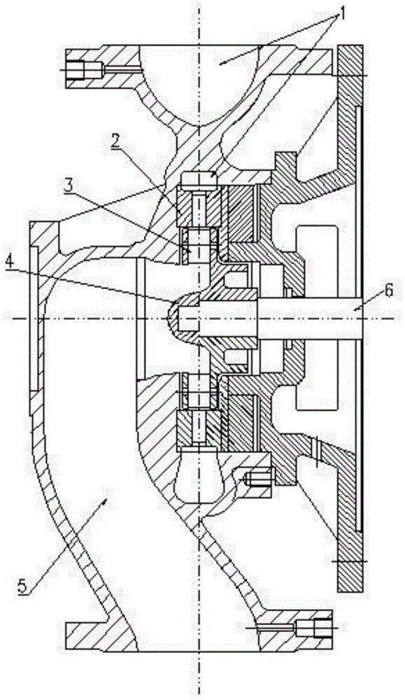
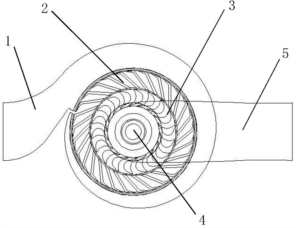
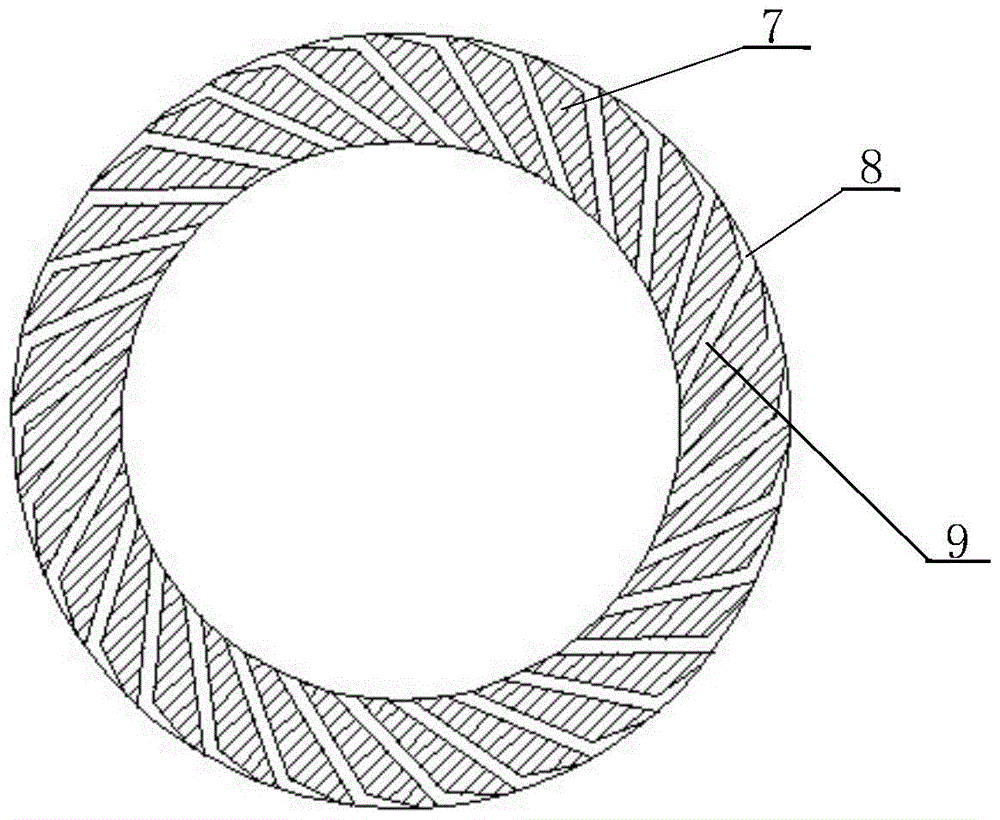
[0024] see Figure 1 to Figure 11 , the present invention includes a volute chamber 1 and a drainage chamber 2, the drainage chamber 2 is fixed on the volute of the volute chamber 1 by bolts, a rotating shaft 6 is installed on the casing, one end of the rotating shaft 6 is connected to the runner 3, and the other end drives the generator In the drainage chamber 2, several drainage cavities 7 are evenly distributed along the circumferential direction. The drainage cavity is the flow channel through which the fluid flows. The flow channel is divided into a front section flow channel 8 and a rear section flow channel 9. It communicates with the volute chamber 1, and the area of ​​the rear flow channel 9 is constant, and communicates with the runner; the water outlet of the runner 3 is connected with the drain pipe 5. The drain pipe 5 and the volute chamber 1 can be integrally cast together, or can be separately cast and connected by bolts.

[0025] During use, the volute chamber...


PUM


Abstract

The invention relates to a device for recovering pipeline liquid pressure energy. It includes a volute chamber and a drainage chamber. The drainage chamber is fixed on the volute of the volute chamber, and a rotating shaft is installed on the casing. One end of the rotating shaft is connected to the runner, and the other end drives the generator. Several drainage chambers are evenly distributed along the circumference of the drainage chamber. The drainage cavity is the channel through which the fluid flows. The channel is divided into a front channel and a rear channel. The area of ​​the front channel is tapered and communicates with the volute chamber. connected; the water outlet of the runner is connected to the drain pipe. The beneficial effect of the present invention is: the decompression device is equipped with a volute chamber and a drainage chamber, while effectively reducing the pipeline pressure, it can efficiently recover the pressure energy of the fluid in the pipeline, and the energy recovery efficiency is ≥ 65%.

Description

technical field [0001] The utility model relates to a pipeline water energy recovery device, which relates to a pipeline liquid pressure energy recovery device. Background technique [0002] At present, in the published literature, many water energy recovery devices are installed on water pipes to generate electricity. The main component of the water energy recovery device is the runner, which is driven by the water flow to rotate the runner, thereby driving the generator to generate electricity. This type of device is more suitable for some pipelines with high pressure and large flow, and has high energy recovery efficiency. However, when the pipe diameter is small (diameter 50-100mm) and the liquid pressure energy is small (water head 20-80m), more energy will be lost, and the recovery efficiency is low, generally less than 50%. Contents of the invention [0003] The problem to be solved by the present invention is to provide a device capable of effectively decompressin...

Claims


Application Information

Patent Timeline
Patent Type & Authority Patents(China)
IPC IPC(8): F03B13/00F03B3/18F03B3/14
Inventor 张惟斌余波邓万权
Owner XIHUA UNIV
Why Eureka
Try Eureka