Method and apparatus for tube bender set-up

a tube bender and tube technology, applied in metal-working apparatus, metal-working devices, shape safety devices, etc., can solve problems such as production inefficiencies and damage to the wiper die itsel

Inactive Publication Date: 2013-09-17
GM GLOBAL TECH OPERATIONS LLC
View PDF6 Cites 0 Cited by
  • Summary
  • Abstract
  • Description
  • Claims
  • Application Information

AI Technical Summary

Problems solved by technology

Traditionally, however, wiper die set-up is an iterative trial and error process, which may lead to production inefficiencies, as well as result in damage to the wiper die itself.

Method used


Image

  • Method and apparatus for tube bender set-up
  • Method and apparatus for tube bender set-up
  • Method and apparatus for tube bender set-up

Examples


Embodiment Construction

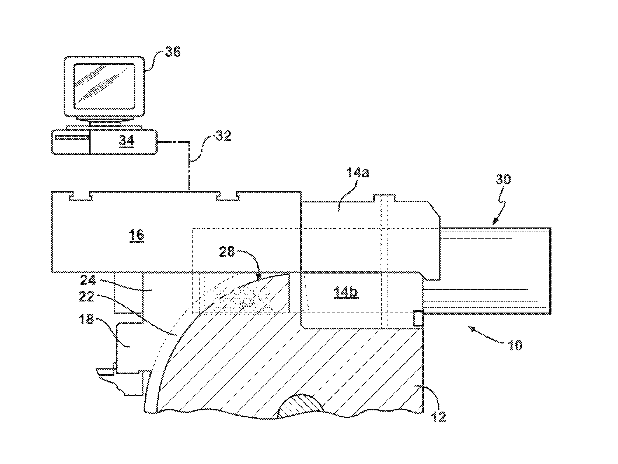
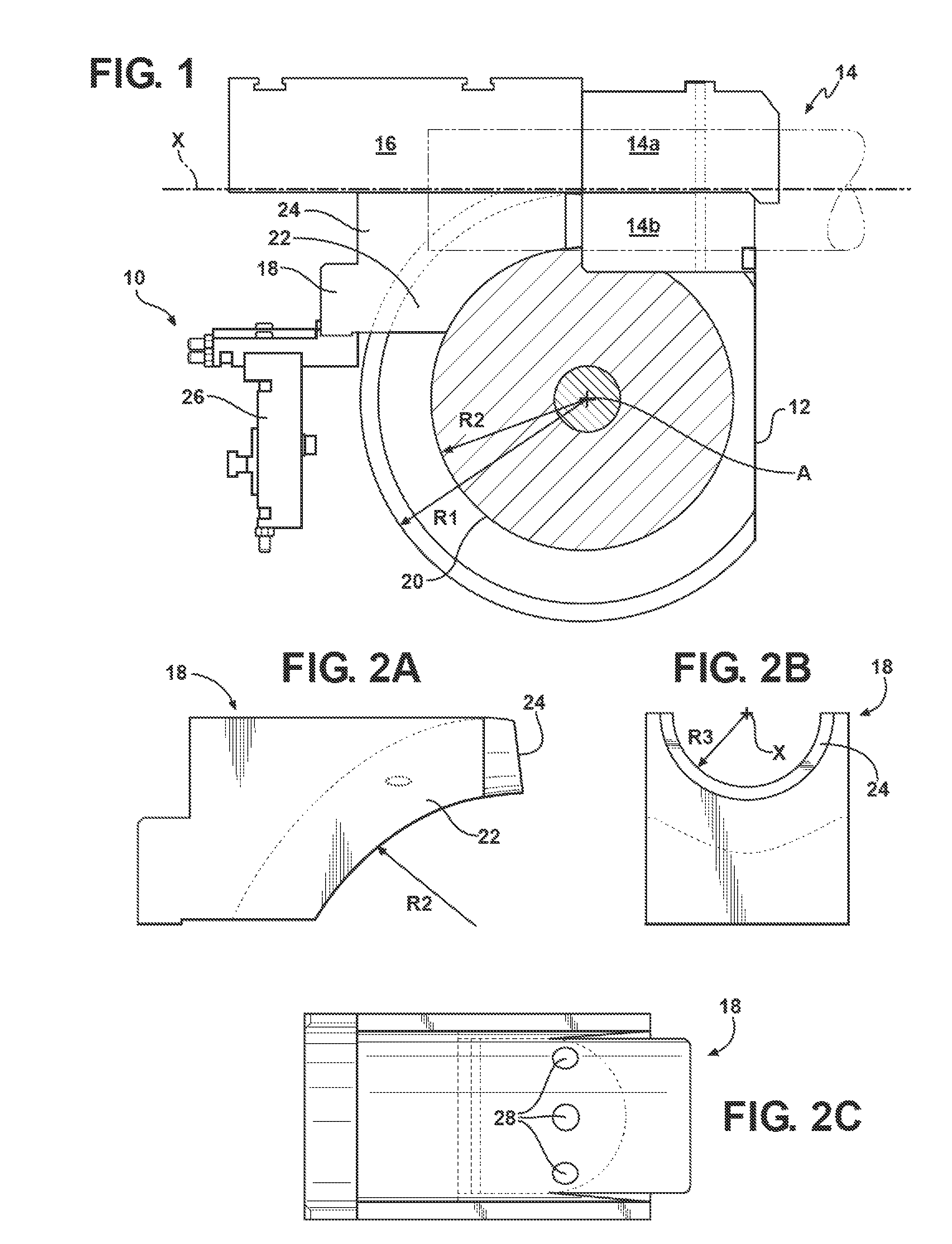
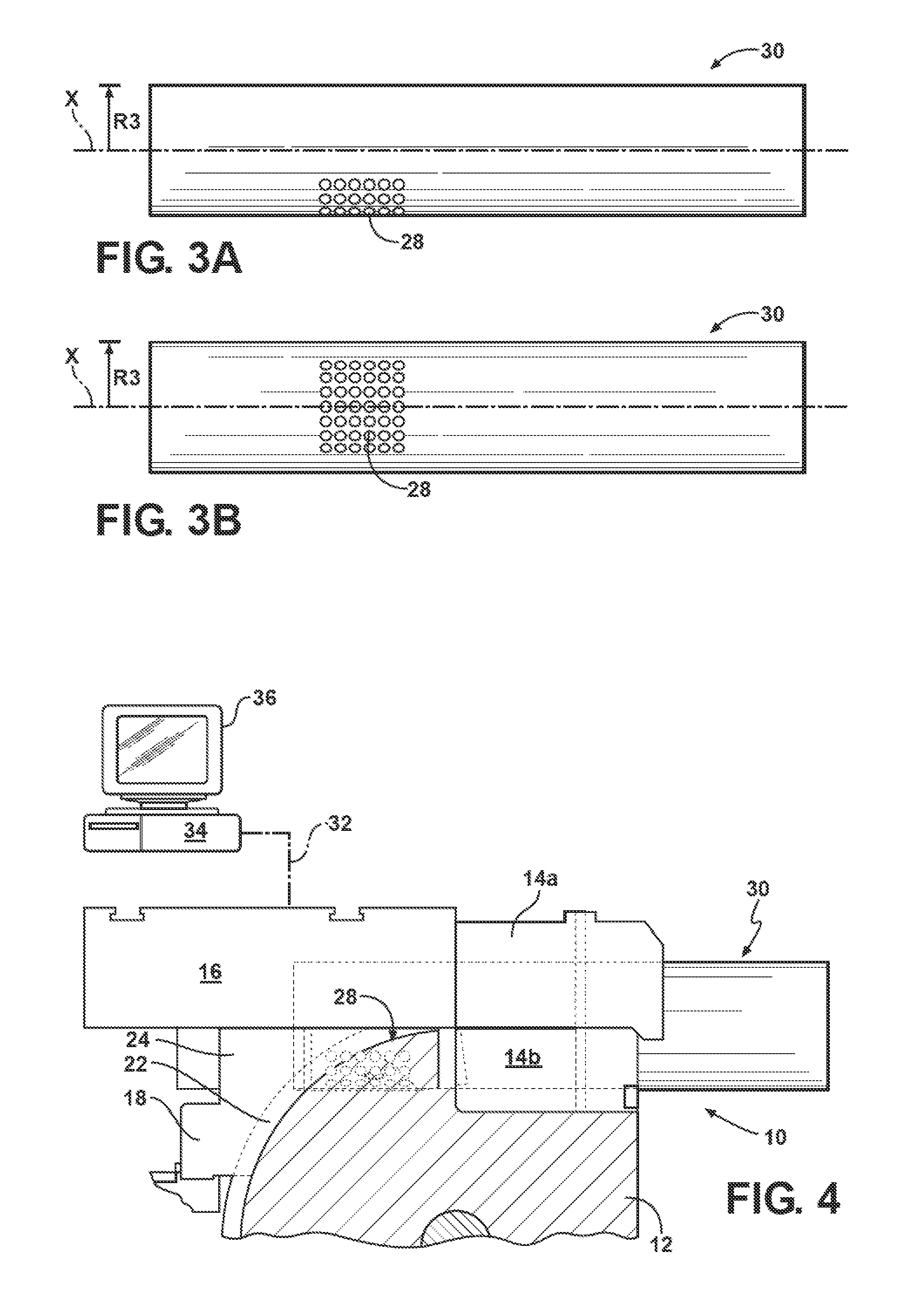
[0016]Referring to the drawings in which like elements are identified with identical numerals throughout, FIG. 1 illustrates a rotary tube bender 10. The tube bender 10 includes a bend die 12, a clamp die 14, a pressure die 16, and a wiper die 18, as known by those skilled in the art. The tube bender 10 is commonly employed in the metal working industry to generate quality bends of a predetermined radius in pipes or tubes that are typically formed from high strength, but malleable materials such as steel or aluminum.

[0017]The bend die 12 has a largely circular shape with an outer radius R1, and is rotationally moveable with respect to an axis A. The bender 10 additionally has a circular guide surface 20 mounted on the axis A, concentrically with respect to the bend die 12. The guide surface 20 has an outer radius R2, with which it serves to position the wiper die 18 in the bender 10. The clamp die 14 mounts relative to bend die 12, and includes a replaceable block 14a and an adjusta...


PUM

PropertyMeasurementUnit
lengthaaaaaaaaaa
forceaaaaaaaaaa
forcesaaaaaaaaaa

Abstract

A method is provided for setting up a tube bender having a bend die, a clamp die, a pressure die and a wiper die. The method includes providing a test-piece having an outer surface defined by a length and a substantially round cross-section. The method also includes arranging the pressure die, the clamp die, and the wiper die relative to each other in the tube bender, and arranging the test-piece relative to the pressure die, the clamp die, and the wiper die. The method further includes applying a force by the tube bender to clamp the test-piece, and determining whether the applied force is within a predetermined range of forces. Additionally, the method includes adjusting the arrangement of at least one of the pressure die, the clamp die, and the wiper die to apply a force to the test-piece that is within the predetermined range of forces.

Description

TECHNICAL FIELD[0001]The present invention relates to tube and pipe bending, and, more particularly, to setting up a tube bender.BACKGROUND OF THE INVENTION[0002]Horizontal rotary draw bending is a commonly employed method utilizing tube bending machines for bending and shaping metal pipes and tubing. Horizontal rotary draw bending machines typically include a bend die, a pressure die, and commonly also a wiper die for restraining the subject tubing in a particular orientation during the bending operation.[0003]Generally, the wiper die is employed for holding tubing in tension, with the aim of preventing possible wrinkling or creasing of the tube wall due to the stress encountered during the operation. Proper setting of the wiper die, the wiper die's fore and aft position and angular orientation, i.e. rake angle, with respect to a bend die, is highly important to the quality of resultant bent tubing. Traditionally, however, wiper die set-up is an iterative trial and error process, w...

Claims


Application Information

Patent Timeline
Patent Type & Authority Patents(United States)
IPC IPC(8): B21D9/00B21D9/04B21D55/00B21D9/05B21D7/04B21C51/00
CPCB21D7/024
Inventor GHIRAN, MIKE M.MELLAS, SPYROS P.CRANTAS, WILLIAM M.MARKS, KEVIN R.WOHLENHAUS, DOUGLAS T.
Owner GM GLOBAL TECH OPERATIONS LLC
Why Eureka
Try Eureka