Apparatus, method, and system for monitoring of equipment and earth ground systems

Active Publication Date: 2013-09-17
MUSCO
22 Cites 10 Cited by

AI-Extracted Technical Summary

Problems solved by technology

Over time, the effectiveness of grounding components in an electrical system may be diminished for a variety of reasons.
Currently available methods of measuring system impedance, while generally adequate wh...

Benefits of technology

[0007]Over time, the effectiveness of grounding components in an electrical system may be diminished for a variety of reasons. Currently available methods of measuring system impedance, while generally adequate when an electrical system is first installed, may become cost-prohibitive and ineffective over the life of the electrical system and, thus, inadequate to determine grounding component effectiveness long-term. Envisioned are apparatus, methods, and systems whereby grounding components of an electrical system may be monitored ...

Abstract

Disclosed are apparatus, methods, and systems for the monitoring of grounding components in an electrical system. Methods of monitoring grounding components comprise a signal or plurality of signals imposed on a ground loop circuit by a first inductive element, a second inductive element which receives the signal(s), and circuitry which compares changes in the imposed signal(s) to a baseline to calculate impedance. Active monitoring of impedance enables contractors to ensure installation of a grounding system was performed correctly, and allows a user to track changes in impedance over the life of the electrical system such that, if an impedance threshold is reached, appropriate action may be taken.

Application Domain

Substation earthing arrangementsArrangements responsive to excess current +3

Technology Topic

InductorActive monitoring +3

Image

  • Apparatus, method, and system for monitoring of equipment and earth ground systems
  • Apparatus, method, and system for monitoring of equipment and earth ground systems
  • Apparatus, method, and system for monitoring of equipment and earth ground systems

Examples

  • Experimental program(2)

Example

B. Exemplary Method and Apparatus Embodiment 1
[0058]A more specific exemplary embodiment, utilizing aspects of the generalized example described above, will now be described. An electrical system such as that illustrated in FIGS. 2A-2C is enabled with a ground monitoring system (GMS) module as illustrated in FIGS. 4A-4D. The GMS module comprises a series of toroids the functionality of which are illustrated in FIGS. 3A and 3B.
[0059]In this embodiment each pole60 has two conductors (25 and 56) which run from a pole cabinet 46 to a contactor cabinet 45. A first ground loop circuit comprises loop grounding bar 36, conductor 56, ground lug 62, section of earth ground wire 27, pole cabinet ground bar 35, equipment ground wire 25, contactor cabinet ground bar 34, and GMS module 80. A second ground loop circuit comprises GMS module 80, equipment ground wire 24, contactor cabinet ground bar 34, service cabinet ground bar 33, service cabinet 44, conduit 23, and contactor cabinet 45; note service cabinet 44, conduit 23, and contactor cabinet 45 are electrically conductive to facilitate a complete electrical connection in the ground loop circuit.
[0060]As can be seen from FIG. 4C, each conductor entering GMS module 80 (e.g. conductor sections 24 and 25 from ground bar 34 to GMS module 80 illustrated in FIG. 2C) passes through a first toroid 20 and second toroid 21 before landing at lug 71. First toroid 20 imposes a signal on the conductor (and thus, the ground loop circuit) and second toroid 21 receives said signal. FIG. 3A diagrammatically illustrates the functionality of first toroid 20, which may generally be characterized by the following. [0061] 1. A 120 to 24 VAC voltage transformer 8 powers a DC power supply 7 which, in turn, powers a crystal oscillator circuit (OSC) 3. [0062] 2. OSC circuit 3 produces a first voltage signal at 1.66 kHz with a square waveform. [0063] a. OSC 3 further acts as a 20 MHz clock input for the multiplexer output circuit. The use of OSCs as clock signals for integrated circuits is well known in the art. [0064] 3. The 1.66 kHz square wave from OSC 3 is converted to a sine wave by a sine wave generator 9. [0065] 4. An analog transmitter 10 directs the voltage signal to any one of a plurality of channels (shown to be five in FIGS. 3A and 3B, though this is by way of example and not by way of limitation) as determined by a processor module 1. [0066] a. An inherent benefit of analog transmitter 10/processor module 1 is such that a single ground loop circuit may be isolated, its impedance measured, and results displayed. Further, the energy required to run the multiplexer output circuit is minimized since only one toroid 20 is energized at a given time. However, other transmitter 10/processor 1 setups may be utilized without realizing the aforementioned benefits and still provide the necessary functionality for the exemplary embodiment. [0067] 5. The constant voltage signal is amplified by a power amplification circuit 15, maintaining a frequency of 1.66 kHz, and used to energize first toroid 20. [0068] 6. The constant voltage signal, at a frequency of 1.66 kHz, is imposed on a ground wire (see reference nos. 24 and 25) running through toroid 20. [0069] 7. A second voltage signal according to the above process is produced at 0.83 kHz and imposed on the ground wire (see reference nos. 24 and 25) running through toroid 20.
[0070]With respect to processor module 1, functionality further comprises calculation of ground loop circuit impedance, comparison of ground loop circuit impedance to threshold levels, display of ground loop circuit impedance values, and communication with a control system (whether remotely operated or otherwise). Processor module 1 may comprise any commercially available microcontroller (e.g. model UPSD 3233B-40U6 available from STMicroelectronics, Geneva, Switzerland) or analogous device.
[0071]Generally, the signal traveling through the ground loop circuit may be imposed at any frequency (given circuitry to impose and receive the signal at said frequency). However, if it is desirable for the ground monitoring system as envisioned to be integrated with other systems which may regulate power to the electrical system to allow for corrective action of an alarm condition (e.g. ground-fault circuit interrupters (GFCIs)), it may be beneficial for the frequency of the imposed signal to reflect that of the incoming power to the electrical system. For example, Underwriters Laboratories Inc. (UL) Guideline KCYC defines the acceptable voltages to ground for different classes of circuits. The electrical system illustrated in FIGS. 2A-C is generally defined as a Class C circuit as the incoming power is typically 480V—three phase at 60 Hz with each conductor measuring 277V to ground (assuming installation in the United States); UL-KCYC defines Class C as a circuit with reliable equipment grounding (per NEC code) with each conductor measuring no more than 300V to ground. Thus, if one were to integrate the ground monitoring system as envisioned with a Class C GFCI device, for the electrical system illustrated in FIGS. 2A-C, one would need to ensure reliable equipment grounding to satisfy the UL-KCYC requirement. As has been stated, the integrity (and thus, reliability) of the equipment grounding may be verified by the ground monitoring system described herein. Thus, for the system illustrated in FIGS. 2A-C operating at 480V—three phase at 60 Hz, it is beneficial to impose a signal at 60 Hz. It is of note, however, that the aforementioned method of determining the frequency of an imposed signal is equally applicable to other electrical systems (e.g. 240V—three phase at 50 Hz, which is common in Europe) and envisioned.
[0072]However, the difficulty in imposing and measuring a signal on a ground loop circuit for the electrical system illustrated in FIGS. 2A-C at 60 Hz is the amount of noise present at that frequency. One solution, then, is to measure impedance at two frequencies, calculate the resistive (R) and inductive (L) components of the impedance, and calculate impedance at 60 Hz (Z60). In the present embodiment signals are imposed and measured at 1.66 kHz and 0.83 kHz as these frequencies are not harmonics of 60 Hz. The calculation of impedance at 60 Hz is described by the following:
Z1=√{square root over (R2+(2πf1L)2)}
Z12=R2+(2πf1L)2
Z2=√{square root over (R2+(2πf2L)2)}
Z22=R2+(2πf2L)2
wherein Z1 is the impedance of the ground loop circuit at a first measurement frequency, R is the resistance of the ground loop circuit, f1 is the first measurement frequency (e.g. 1.66 kHz), L is the inductance of the ground loop circuit, Z2 is the impedance of the ground loop circuit at a second measurement frequency, and f2 is the second measurement frequency (e.g. 0.83 kHz).
[0073]The aforementioned formulas for the impedance of the ground loop circuit at two measurement frequencies may be solved simultaneously to provide the following formulas for the inductance, L, and the resistance, R, of the ground loop circuit.
[0074] Z 1 2 - Z 2 2 = ⁢ R 2 + ( 2 ⁢ π ⁢ ⁢ f 1 ⁢ L ) 2 - R 2 - ( 2 ⁢ π ⁢ ⁢ f 2 ⁢ L ) 2 = ⁢ ( 2 ⁢ π ⁢ ⁢ f 1 ⁢ L ) 2 - ( 2 ⁢ π ⁢ ⁢ f 2 ⁢ L ) 2 = ⁢ L 2 ⁡ [ ( 2 ⁢ π ⁢ ⁢ f 1 ) 2 - ( 2 ⁢ π ⁢ ⁢ f 2 ) 2 ] L = Z 1 2 - Z 2 2 ( 2 ⁢ π ⁢ ⁢ f 1 ) 2 - ( 2 ⁢ π ⁢ ⁢ f 2 ) 2 Z 1 = R 2 + ( 2 ⁢ π ⁢ ⁢ f 1 ⁢ L ) 2 Z 1 2 = R 2 + ( 2 ⁢ π ⁢ ⁢ f 1 ⁢ L ) 2 R = Z 1 2 - ( 2 ⁢ π ⁢ ⁢ f 1 ⁢ L ) 2 R = Z 1 2 - ( 2 ⁢ π ⁢ ⁢ f 1 ) 2 ⁢ ( Z 1 2 - Z 2 2 ( 2 ⁢ π ⁢ ⁢ f 1 ) 2 - ( 2 ⁢ π ⁢ ⁢ f 2 ) 2 )
[0075]The calculated formulas for the inductance L, and resistance, R, may then be substituted for said variables in the original equation and solved for the impedance of the ground loop circuit (Z60) at a frequency of 60 Hz (f60).
[0076] ⁢ Z 60 = R 2 + ( 2 ⁢ π ⁢ ⁢ f 60 ⁢ L ) 2 ⁢ Z 60 = R 2 + ( 2 ⁢ π ⁢ ⁢ 60 ⁢ L ) 2 Z 60 = ( Z 1 2 - ( 2 ⁢ π ⁢ ⁢ f 1 ) 2 ⁢ ( Z 1 2 - Z 2 2 ( 2 ⁢ π ⁢ ⁢ f 1 ) 2 - ( 2 ⁢ π ⁢ ⁢ f 2 ) 2 ) ) 2 + ( ( 2 ⁢ π ⁢ ⁢ 60 ) 2 ⁢ ( Z 1 2 - Z 2 2 ( 2 ⁢ π ⁢ ⁢ f 1 ) 2 - ( 2 ⁢ π ⁢ ⁢ f 2 ) 2 ) 2 ) Z 60 = ( Z 1 2 - ( 2 ⁢ π ⁢ ⁢ f 1 ) 2 ⁢ ( Z 1 2 - Z 2 2 ( 2 ⁢ π ⁢ ⁢ f 1 ) 2 - ( 2 ⁢ π ⁢ ⁢ f 2 ) 2 ) ) 2 + ( ( 120 ⁢ π ⁢ ) 2 ⁢ ( Z 1 2 - Z 2 2 ( 2 ⁢ π ⁢ ⁢ f 1 ) 2 - ( 2 ⁢ π ⁢ ⁢ f 2 ) 2 ) )
[0077]The imposed voltage signals induce current in a second toroid 21 of each ground loop circuit being monitored, the functionality of which is diagrammatically illustrated in FIG. 3B and may generally be characterized by the following. [0078] 1. The induced current produces a small voltage in second toroid 21. [0079] 2. A receiver circuit 16 amplifies and buffers the signal front toroid 21. [0080] 3. An analog receiver 11, as directed by processor module 1, routes the signal to a notch filter 4 which filters out noise from the voltage signal to isolate the frequency of interest (e.g. 1.66 kHz for the first frequency and 0.83 kHz for the second frequency), with a pass bandwidth of ±100 Hz. [0081] 4. The signal is converted from AC to DC by a RMS to DC converter 5. [0082] 5. The DC signal is then converted by a 12-bit analog to digital converter 6 from an analog waveform to a binary code, which is processed and stored by processor module 1. [0083] Ground loop circuit impedance is measured at the time of installation, thus providing a baseline value. When second toroid 21 is energized and produces a signal to the multiplexer input circuit, any changes in ground loop circuit impedance are reflected in the value of said signal. Thus, knowing the imposed constant voltage (at both 1.66 kHz and 0.83 kHz), the measured second toroid signal (at both 1.66 kHz and 0.83 kHz), and the ground loop circuit baseline impedance, processor module 1 is able to calculate changes in impedance of the ground loop circuit at 60 Hz by calculations well known in the art and previously described.
[0084]Activation of the multiplexer input and output circuits may be enabled by a remote operation functionality (e.g. CONTROL-LINK®) at regularly scheduled intervals, or when deemed necessary by a control center 90 or by a user. Alternatively, or in addition, activation of the multiplexer input and output circuits may be enabled onsite by a user interface on GMS module 80. One possible user interface and housing for GMS module 80 is illustrated in FIGS. 4A-4D and may generally be characterized by the following. [0085] A housing 70 which may display user interface functionality comprising: [0086] A pair of pushbuttons 76 which toggle through the channels in processor module 1, [0087] Note that there may be any number of channels available but at least enough such that each ground loop circuit has a dedicated channel. For example, FIG. 4C illustrates five conductors entering five pairs of toroids. Thus, for this example there would be at least five channels available. [0088] A display 77 to illustrate which channel is active, [0089] A display 73 to illustrate the impedance value for the active channel, [0090] A pair of LEDs 72 (e.g. one green and one red) to visually indicate alarm status (e.g. green to indicate sufficient ground loop circuit impedance and red to indicate an alarm notification), [0091] A pushbutton 75 which, when pressed, displays an instantaneous maximum impedance value (as indicated by channel display 77 and value display 73 for the channels in processor module 1 for a finite period of time (e.g. two seconds), and then displays an instantaneous minimum impedance value (as indicated by channel display 77 and value display 73 for the channels in processor module 1) for a finite period of time (e.g. two seconds), [0092] A pushbutton 74 which, when pressed, may erase impedance values stored in processor module 1 and reset max/min values, [0093] A pushbutton 79 which, when pressed, will initiate operation of the multiplexer input and output circuits, as was described for FIGS. 3A and 3B, and display the results on channel display 77 and value display 73 for each channel in processor module 1 for a finite period of time (e.g. two seconds for each channel); and, [0094] An optional pushbutton 78 which, when pressed, may display alternative data on value display 73. [0095] A series of landing lugs 71 for each channel (shown by way of example and not by way of limitation to be five lugs for five incoming conductors, each of which has a dedicated channel). [0096] A first toroid 20 and a second toroid 21, the functionality of which was described for FIGS. 3A and 3B, for each channel.
[0097]It is of note that the alternative data available via the optional pushbutton 78 may vary depending on the application. For example, in many applications it may be beneficial for an electrical system such as that illustrated in FIGS. 2A-C to comprise methods of disabling power to components of the electrical system (e.g. via GFCI) if component impedance increases to an unacceptable threshold, in addition to monitoring and reporting such conditions. If such were the case, optional pushbutton 78 may allow data relevant to GFCI functionality (e.g. leakage current) to be displayed. As a further example, display of information relevant to the application layout may be enabled by optional pushbutton 78 (e.g. ground wire size, earth ground electrode material, etc.).
[0098]The present exemplary embodiment detects the presence and functionality of the grounding components of the electrical system illustrated in FIGS. 2A-C including equipment ground electrode 28, equipment ground wire 29, equipment ground wire 24, and connections associated with the service cabinet 44 and contactor cabinet 45 via the second ground loop circuit as previously described; as well as the equipment ground wire 25, conductor 56, section of earth ground wire 27 spanning lug 62 to ground bar 35, and connections associated with each pole 60 via the first ground loop circuit as previously described.
[0099]A primary benefit of the exemplary embodiment as described is such that a reliable ground is ensured for the electrical system illustrated in FIGS. 2A-C (thus adhering to UL Class C requirements). Additionally, if it is desirable for the electrical system illustrated in FIGS. 2A-C to further comprise systems which may regulate power to the electrical system to allow for corrective action of an alarm condition (e.g. GFCIs), active monitoring of the grounding components allows the voltage to ground to be limited to a specified value (thus adhering to UL KCYC requirements).

Example

C. Exemplary Method and Apparatus Embodiment 2
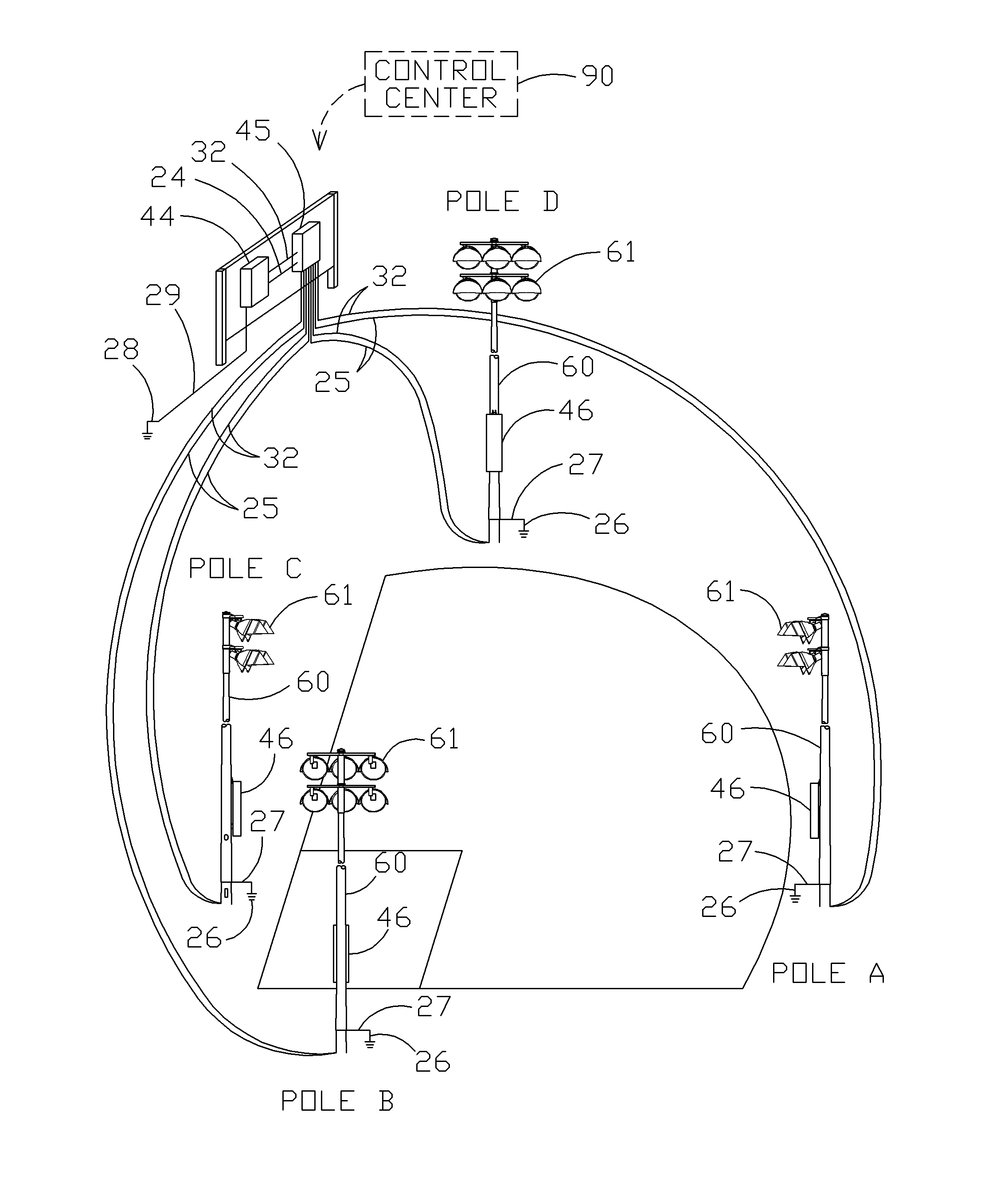
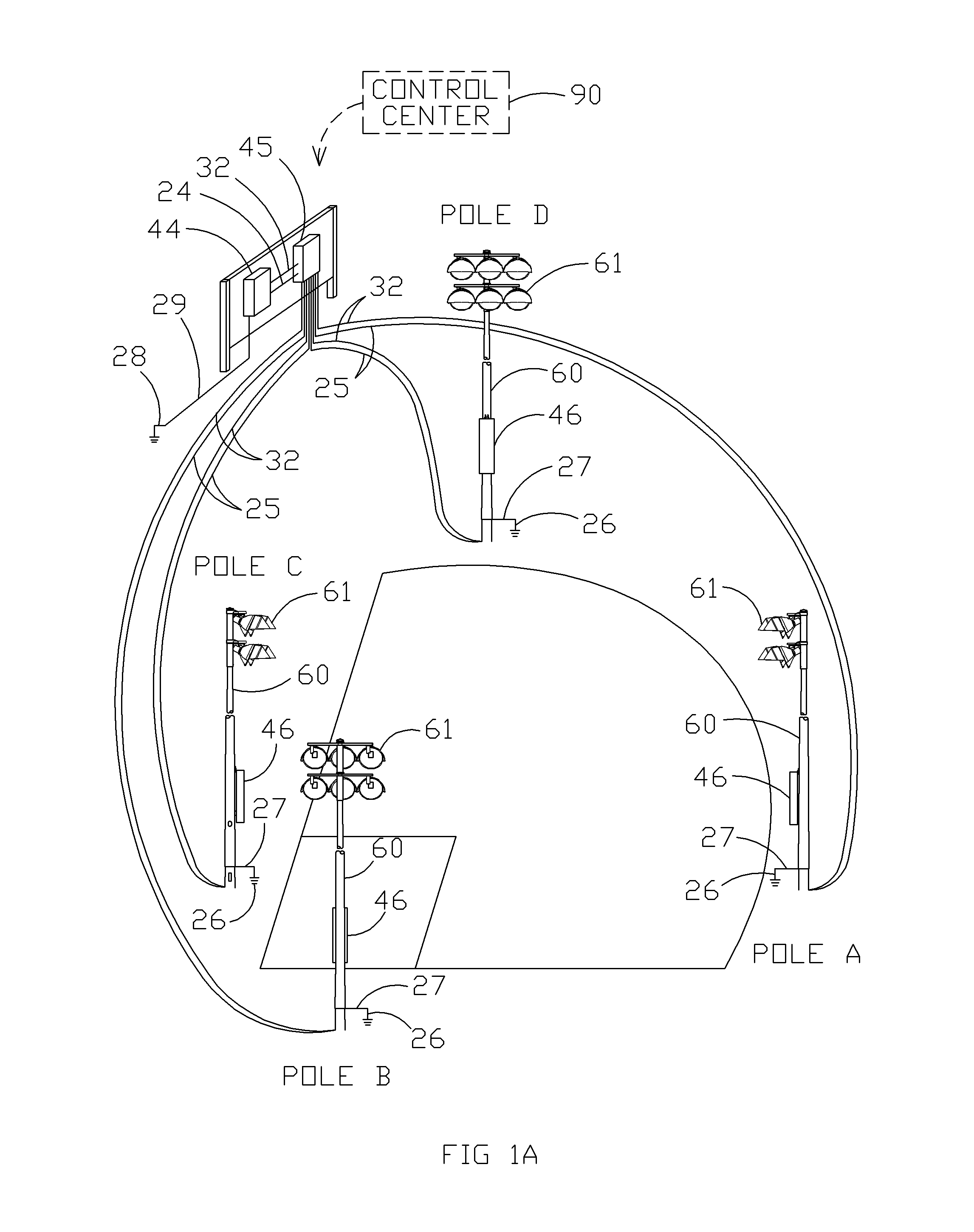
[0100]An alternative embodiment of the invention envisions an electrical system such as that illustrated in FIGS. 1A, 5A, and 5B enabled with a GMS module as illustrated in FIGS. 4A-4D. The GMS module comprises a series of toroids the functionality of which is described in Exemplary Method and Apparatus Embodiment 1.
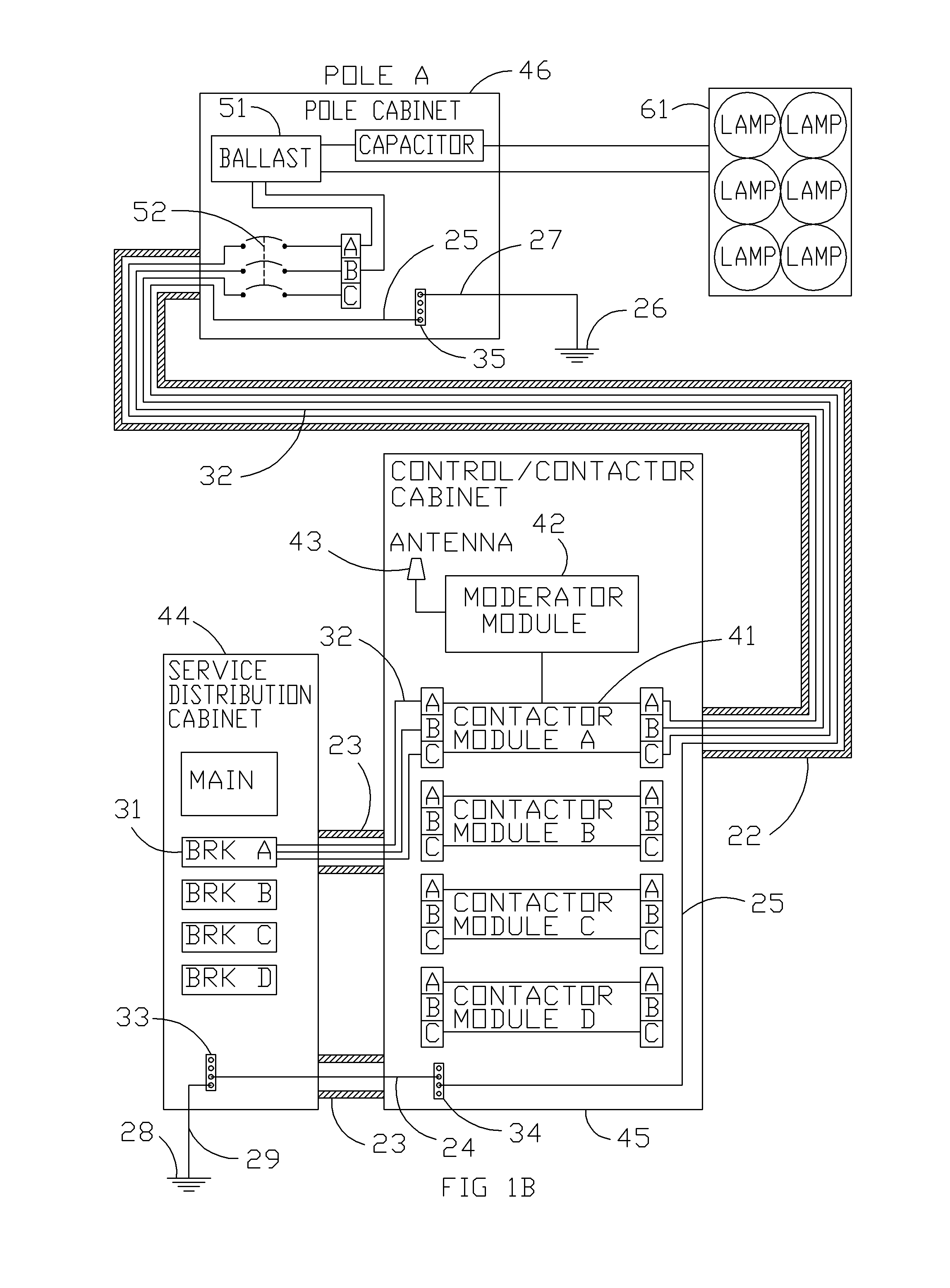
[0101]Similar to Exemplary Method and Apparatus Embodiment 1, in this embodiment the electrical system has two ground loop circuits. The first ground loop circuit comprises GMS module 80, equipment ground wire 25, contactor cabinet ground bar 34, pole cabinet ground bar 35, earth ground wire 27, pole ground lug 62, earth ground electrode 26, earth 100, equipment ground electrode 28, equipment ground wire 29, cabinet ground bar 33, and equipment ground wire 24. Note that the flow of an imposed signal from electrode 26 to electrode 28 via earth 100 is diagrammatically illustrated by a dashed line in FIG. 5B. The first ground loop circuit detects the presence and functionality of grounding components of the electrical system illustrated in FIGS. 1A, 5A, and 5B including equipment ground wire 25, earth ground wire 27, earth ground electrode 26, connections associated with each pole 60, equipment ground electrode 28, and equipment ground wire 29. The second ground loop circuit in this embodiment is the same as the second ground loop circuit in Exemplary Method and Apparatus Embodiment 1.
[0102]A primary benefit of the exemplary embodiment as described is such that one can determine if poles are properly grounded without extensive testing or digging up electrodes. Whereas the benefits in Exemplary Method and Apparatus Embodiment 1 are of a personal protection nature, the benefits in the present embodiment are of an equipment longevity nature.
D. Options and Alternatives
[0103]The invention may take many forms and embodiments. The foregoing examples are but a few of those. To give some sense of some options and alternatives, a few examples are given below.
[0104]Generally, the exemplary embodiments described herein illustrate a complete electrical circuit for a single bank of light fixtures (see FIG. 1B). It is of note, however, that this is by way of example and not by way of limitation. For example, those skilled in the art would know that moderator module 42 may regulate all of the contactor modules within control/contactor cabinet 45, and/or a pole cabinet 46 and the components therein may power a plurality of fixtures 61. As a further example, a single control center 90 may enable remote operation of a plurality of GMS modules 80, thus facilitating active monitoring of grounding systems at multiple equipment locations from a single point.
[0105]Further, the methods of monitoring and testing grounding components described herein may be applied to electrical systems other than those illustrated in the exemplary embodiments (e.g. street lighting, food display cases, HVAC units) without departing from at least some aspects of the invention. For example, an electrical system similar to those illustrated and referenced herein, but not adhering to UL class requirements (e.g. Class C, KCYC), may still glean benefits (e.g. personal protection from electrical shock hazards) from aspects of the invention.
[0106]Generally, the exemplary embodiments described herein illustrate remote operation of GMS module 80 enabled by control center 90, a specific example of which is commercially available from Musco Sports Lighting, LLC under the trade name CONTROL-LINK®. However, it is of note that the remote operation functionality may comprise any methods of communicating between GMS module 80 and a central server and is not limited to CONTROL-LINK®.
[0107]Further, location of GMS module 80 is not limited to those illustrated in the exemplary embodiments. For example, if the application is a food display case there may not be a contactor cabinet 45 in which to house GMS module 80—some other enclosure may be available. Aspects according to the invention (e.g. imposing and receiving a signal to determine impedance, determining trends in system impedance over time, etc.) are equally applicable to systems which comprise components other than those described herein (e.g. light fixtures 61), house GMS module 80 in alternative locations, and/or comprise ground loop circuits other than those described herein.

PUM

no PUM

Description & Claims & Application Information

We can also present the details of the Description, Claims and Application information to help users get a comprehensive understanding of the technical details of the patent, such as background art, summary of invention, brief description of drawings, description of embodiments, and other original content. On the other hand, users can also determine the specific scope of protection of the technology through the list of claims; as well as understand the changes in the life cycle of the technology with the presentation of the patent timeline. Login to view more.

Similar technology patents

Two ball, ball striking trainer

ActiveUS20210001198A1high likelihooddiminish their effectiveness
Owner:COCHRAN HAYDEN A

Classification and recommendation of technical efficacy words

  • diminish their effectiveness

Two ball, ball striking trainer

ActiveUS20210001198A1high likelihooddiminish their effectiveness
Owner:COCHRAN HAYDEN A
Why Eureka
Try Eureka