Collapsible intravenous fluid pole system

a fluid pole system, collapsible technology, applied in the direction of machine supports, furniture parts, washing stands, etc., can solve the problems of difficult storage and transportation

Inactive Publication Date: 2013-10-29
STEVENSON CHERIE
View PDF15 Cites 37 Cited by
  • Summary
  • Abstract
  • Description
  • Claims
  • Application Information

AI Technical Summary

Problems solved by technology

Intravenous fluid poles are large and cumbersome pieces of equipment, and they can be difficult to store and transport.

Method used


Image

  • Collapsible intravenous fluid pole system
  • Collapsible intravenous fluid pole system
  • Collapsible intravenous fluid pole system

Examples


Embodiment Construction

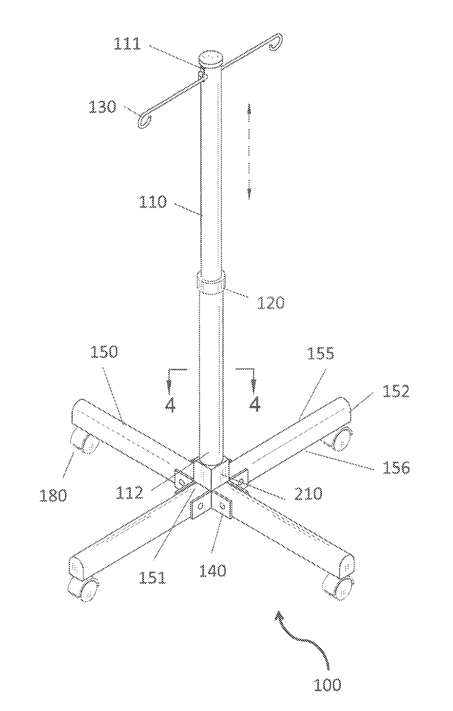
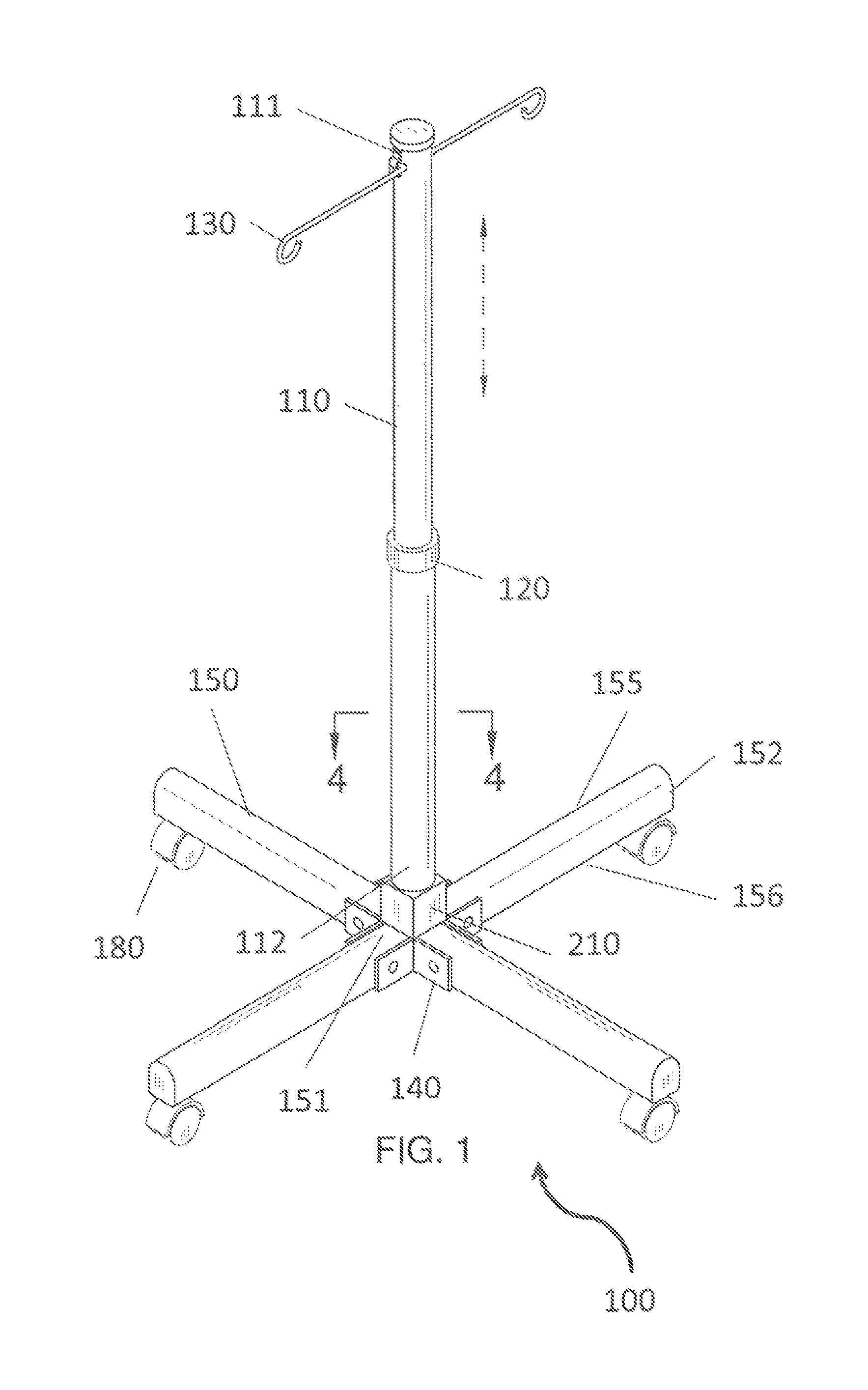
[0013]Referring now to FIG. 1-7, the present invention features a novel intravenous fluid pole system (100) that collapses and can be easily stored or transported. The system (100) comprises a shaft (110) having a top end (111) and a bottom end (112). The shaft (110) can expand and contract to achieve a desired length. For example, the shaft (110) is a telescopic pole that can expand and contract in a standard manner. The shaft (110) can be secured at a particular desired length via a securing means (120), for example a nut that can be rotated in a first direction or a second direction to respectively allow or prevent expansion or contraction of the shaft (110), etc. Telescopic poles and securing means for telescopic poles are well know to one of ordinary skill in the art.

[0014]The system (100) further comprises hangers (130) for attaching (e.g., temporarily attaching) intravenous fluid bags. For example, in some embodiments, a first hanger (130) is pivotally attached to the shaft (...


PUM


Abstract

A collapsible intravenous fluid pole system that can be easily stored or transported featuring a shaft with hangers disposed at the top end, the hangers being for attaching intravenous fluid bags, and legs pivotally attached at the bottom of the shaft. Wheels are disposed on the legs. The hangers can extend from the shaft or collapse to a storage position. The legs can extend or fold upwardly toward the shaft. The legs are attached via extension joints. A locking collar is disposed on the shaft. The locking collar can slide up and down along the shaft and can be inserted into a slot in the tongues of the legs to prevent the legs from folding upwardly to the folded position.

Description

BACKGROUND OF THE INVENTION[0001]Intravenous fluid poles are large and cumbersome pieces of equipment, and they can be difficult to store and transport. The present invention features a novel intravenous fluid pole system that collapses and can be easily stored or transported. For example, the system features a telescopic pole and foldable legs. The intravenous fluid pole system of the present invention may be constructed in designs and styles to appeal to adults and / or children. The system of the present invention may include a storage bag or case.[0002]Any feature or combination of features described herein are included within the scope of the present invention provided that the features included in any such combination are not mutually inconsistent as will be apparent from the context, this specification, and the knowledge of one of ordinary skill in the art. Additional advantages and aspects of the present invention are apparent in the following detailed description and claims.B...

Claims


Application Information

Patent Timeline
Patent Type & Authority Patents(United States)
IPC IPC(8): A47F5/00A47F7/00
CPCA61M5/1415A61M5/1417A61M2209/082A61M2209/084
Inventor STEVENSON, CHERIE
Owner STEVENSON CHERIE
Why Eureka
Try Eureka