Intravenous drip set controller with flusher

a technology of drip set and controller, which is applied in the direction of flow monitors, diaphragm valves, mechanical equipment, etc., can solve the problems of putting the patient's life at risk, and achieve the effect of simple and efficient flushing mechanism, convenient and efficient flushing procedure and convenient operation

Active Publication Date: 2013-10-29
IM HIGH TECH LTD
View PDF3 Cites 3 Cited by
  • Summary
  • Abstract
  • Description
  • Claims
  • Application Information

AI Technical Summary

Benefits of technology

[0010]It is a primary object of the present invention to provide for a built in device in the intravenous drip that can not only regulate the flow but also include a simple and efficient flushing mechanism for the intravenous line. This will facilitate an easy, efficient and regular flushing procedure to be carried out anytime, anywhere on every intravenous line.
[0011]By constantly flushing the intravenous line, it will extend and prolong the life span of any peripheral line and thus minimize the need for setting up another peripheral line. This will in turn help to minimize the extra risk of infection due to the setting up of the peripheral lines repeatedly. When an individual peripheral line's life span is prolonged, it is possible to obviate the need for a central line and venous cut down. which are more invasive and may put the patient's life at risk.
[0012]In short, this device will save time and cost by eliminating the use of syringes for flushing purposes and thereby decreasing the cost needed for setting up of repeated intravenous lines required in each particular case, as well as decreasing generally the rate of morbidity and mortality, which may arise as a complication of the more invasive use of venous cut downs and central lines. It is another object of the present invention to provide an intravenous set flow regulator cum flusher that is both simple to use, reliable and cheap to manufacture.
[0015](b) a fixed roller which rotates on its own axis and together with the mobile roller, engaging the flexible tubing on either side, and squeezing the flexible tubing of the intravenous line into a totally closed position to act as a flusher for the intravenous line, whereby when by sliding the entire unit downwards along the tubing proximally pushing the fluid in the intravenous line towards the patient, the flushing of the fluid in the intravenous line is thereby achieved.

Problems solved by technology

When an individual peripheral line's life span is prolonged, it is possible to obviate the need for a central line and venous cut down. which are more invasive and may put the patient's life at risk.

Method used


Image

  • Intravenous drip set controller with flusher
  • Intravenous drip set controller with flusher
  • Intravenous drip set controller with flusher

Examples


Embodiment Construction

[0025]The present invention relates to a device that functions both as a built in regulator and a flusher for an intravenous drip set. It is attached to the flexible tubing and situated in between the bag and the cannula.

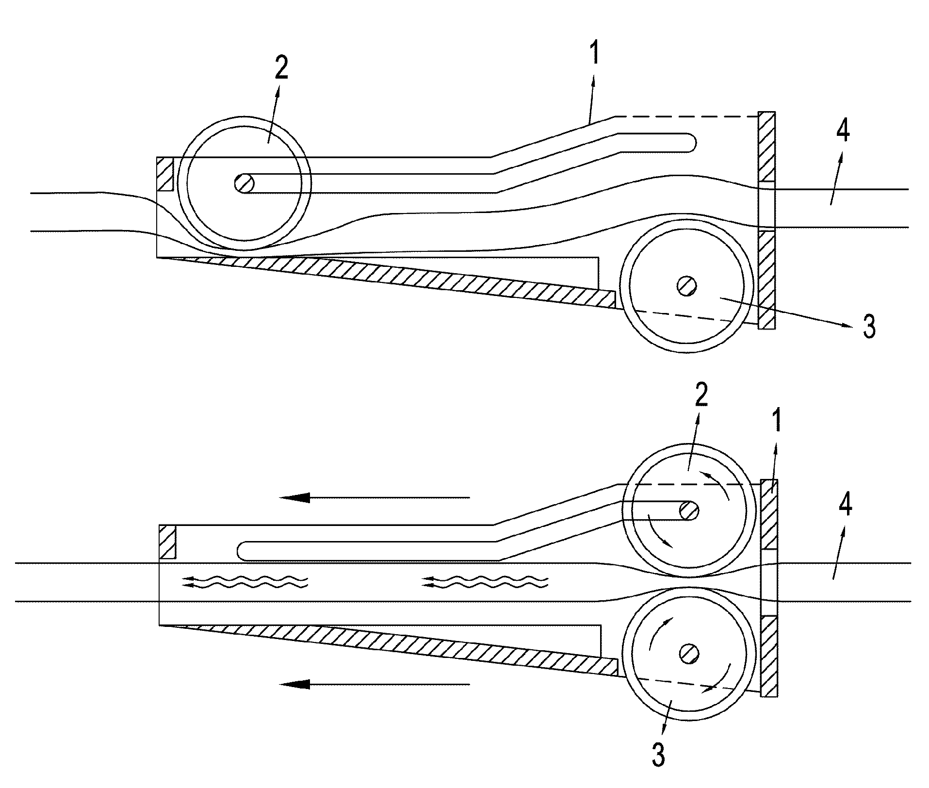
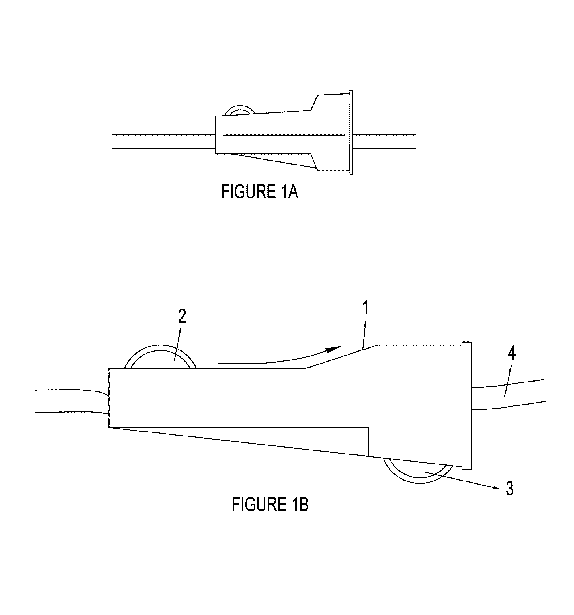
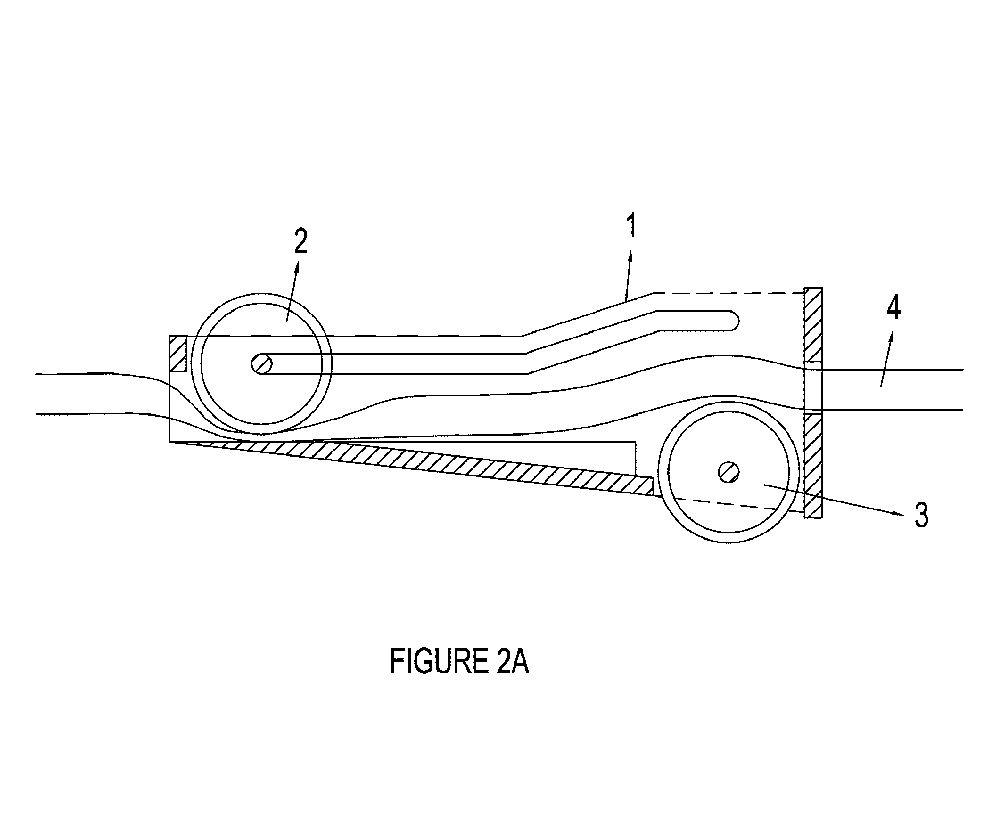
[0026]FIG. 1A shows a conventional intravenous drip regulator, found in prior art, which comprises of a main housing with a mobile roller affixed within. The mobile roller slides diagonally on the intravenous line as it rotates along a groove and rail, all held within the housing, such that as it slides, it gradually compresses the flexible tubing thereby acting as a regulator as it moves along in different positions from one end to the other of the main housing.

[0027]FIG. 1 B shows the present invention, which comprises of a main housing (1) with a mobile roller (2) affixed within a main housing (1), to act as a regulator, it further comprises a fixed roller (3) attached to one end of the main housing (1). The fixed roller rotates on its own axis and together with ...


PUM


Abstract

A regulating device for an intravenous drip set comprising a main housing unit (1) which comprises a mobile roller (2) which can gradually compress a flexible tubing (4) until the tubing (4) is fully compressed and a fixed roller (3) which together with the mobile roller (2) squeeze the flexible tubing of an intravenous line into a totally closed position to act as a flusher for the intravenous line, whereby when by sliding the entire device downwards along the tubing (4) proximally towards a patient, flushing of fluid in the intravenous line is thereby achieved.

Description

RELATED APPLICATIONS[0001]The present application is a 35 U.S.C. §371 national stage filing of International Patent Application No. PCT / MY / 000024, filed Apr. 20, 2007, to which priority is claimed under 35 U.S.C. §120 and through which priority is claimed under 35 U.S.C. §119 to Malaysian Priority Patent Application No. PI2006-2216, filed May 15, 2006.FIELD OF THE INVENTION[0002]This invention relates to an intravenous drip set, and more particularly it relates to an improved monitoring device for controlling the flow and flushing the fluid.BACKGROUND OF THE INVENTION[0003]Intravenous drips are commonly used to administer a continuous flow of fluid to a patient for a predetermined length of time. The intravenous drip set generally includes a bag or container of intravenous fluid that is connected through a series of conduits comprising of flexible tubing, chambers and monitoring devices to a cannula inserted into a vein of the patient. The bag or container is supported at a higher e...

Claims


Application Information

Patent Timeline
Patent Type & Authority Patents(United States)
IPC IPC(8): A61M5/00A61M5/14F16K7/04
CPCA61M5/16881A61M39/286
Inventor CHEW, HENG HAI
Owner IM HIGH TECH LTD
Why Eureka
Try Eureka