
Device for supporting a rotatable target and sputtering apparatus

a sputtering device and rotatable target technology, applied in mechanical instruments, discharge tubes/lamp details, x-ray tubes, etc., can solve the problems of increasing the maintenance cost of the sputtering unit, defective products, and extending the service life of the rotatable targ

Active Publication Date: 2014-01-07
APPLIED MATERIALS INC
View PDF11 Cites 3 Cited by
  • Summary
  • Abstract
  • Description
  • Claims
  • Application Information

AI Technical Summary

Benefits of technology

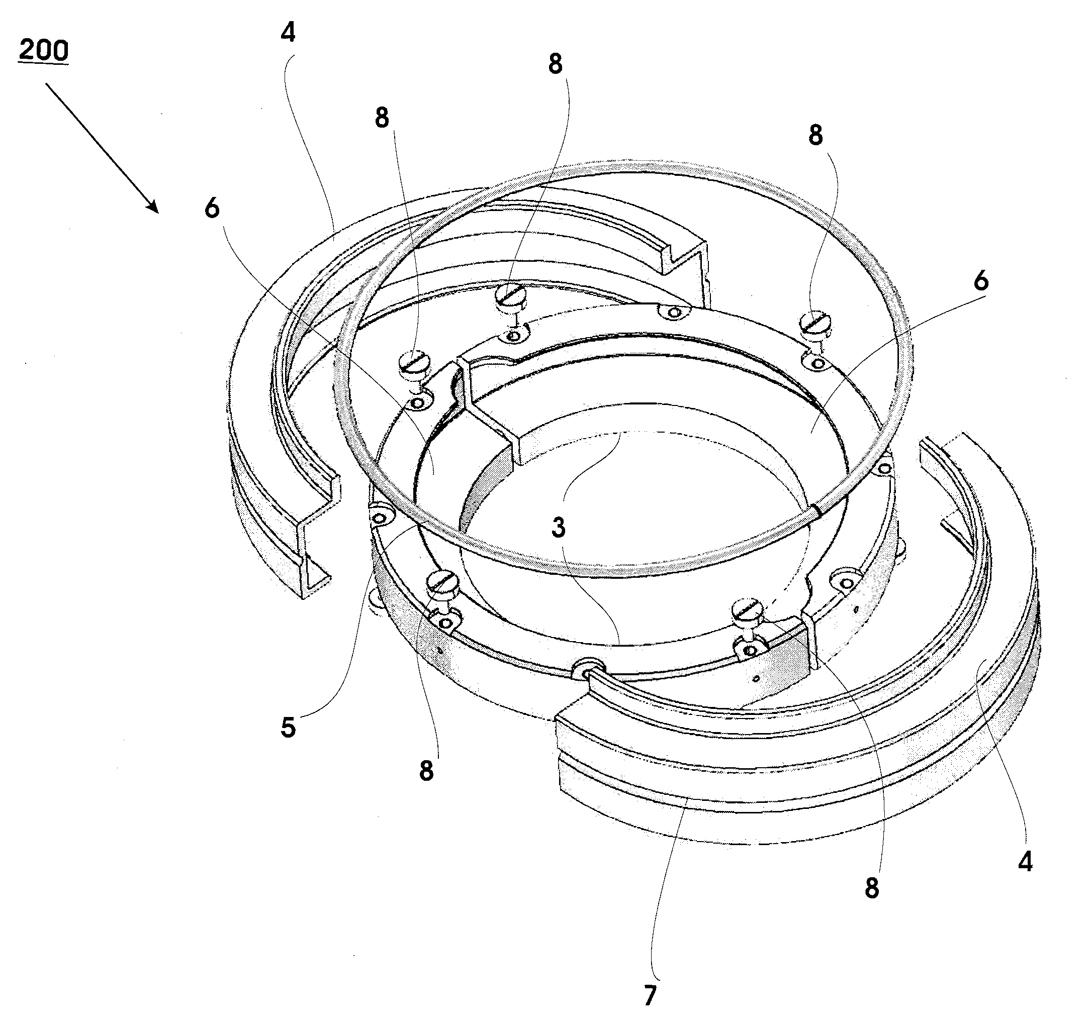
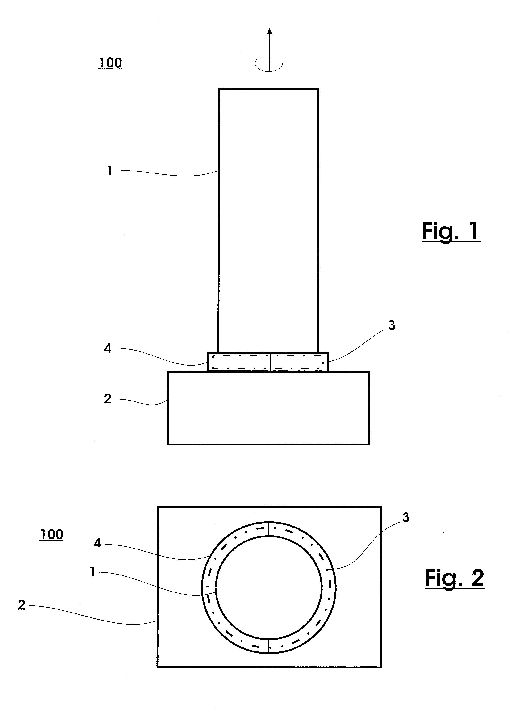
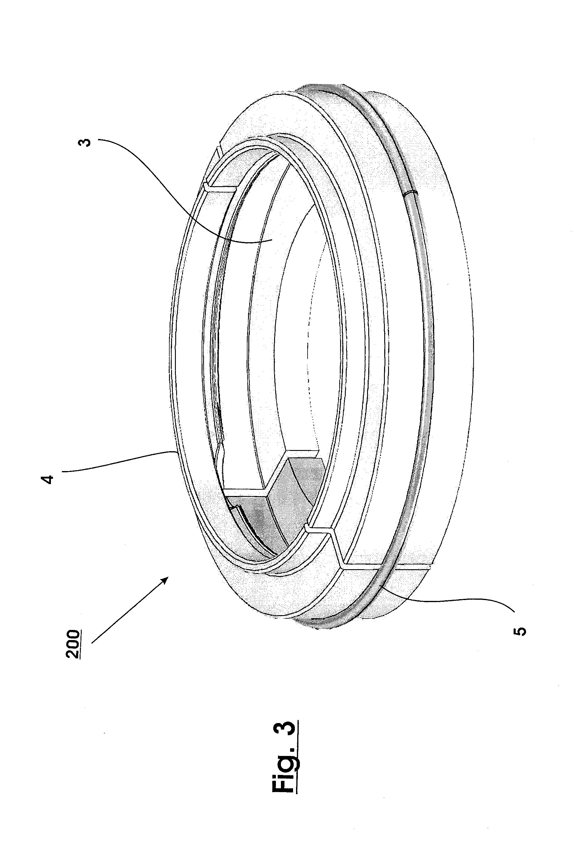
[0011]Some of the above mentioned embodiments will be described in more detail in the following description of typical embodiments with reference to the following drawings in which:

Problems solved by technology

Accordingly, the use of rotatable targets typically prolongs service life and reduces costs.
If the resulting fragments of material fall onto the substrate, they obstruct deposition on the areas of the substrate which they fall on, resulting in defective products.
Therefore, such a dark room shield has to be exchanged often, thus increasing the maintenance costs of the sputtering unit.

Method used


Image

  • Device for supporting a rotatable target and sputtering apparatus
  • Device for supporting a rotatable target and sputtering apparatus
  • Device for supporting a rotatable target and sputtering apparatus

Examples


Embodiment Construction

[0022]Reference will now be made in detail to the various embodiments, one or more examples of which are illustrated in each figure. Each example is provided by way of explanation and is not meant as a limitation. For example, features illustrated or described as part of one embodiment can be used on or in conjunction with other embodiments to yield yet further embodiments. It is intended that the present disclosure includes such modifications and variations.

[0023]Sputtering is a process in which atoms are ejected from a solid target material due to bombardment of the target by energetic particles. The process of coating a substrate as a material at the scraping refers typically to thin film applications. The term “coating” and the term “depositing” are used interchangeably herein. The terms “sputtering installation” and “deposition apparatus” are used interchangeably herein and shall refer to an apparatus which uses sputtering for depositing a target material, typically as a thin f...


PUM

PropertyMeasurementUnit
lengthaaaaaaaaaa
lengthaaaaaaaaaa
diameteraaaaaaaaaa

Abstract

It is provided a device for supporting a rotatable target of a deposition apparatus for sputtering material onto a substrate, wherein the device includes a drive unit for rotating the rotatable target; a ring-shaped part connected to the drive unit for attaching the drive unit to the rotatable target; and, a shield for covering the ring-shaped part. The shield is adapted for rotating together with the ring-shaped part and includes a plurality of parts assembled together. Furthermore, a sputtering apparatus and a method for supporting a rotatable target are provided.

Description

FIELD OF THE INVENTION[0001]The present disclosure relates to a device for supporting a rotatable target, particularly to a device having a target main body, an intermediate part for connecting the target main body to a drive unit for rotating the target and a dark room shield assembled to the intermediate part, and a method for supporting a rotatable target. In particular, embodiments of the present invention relate to nano-manufacturing technology solutions involving equipment, processes, and materials used in the deposition of thin films and coatings, with representative examples including (but not limited to) applications involving: semiconductor and dielectric materials and devices, silicon-based wafers, flat panel displays (such as TFTs), masks and filters, energy conversion and storage (such as photovoltaic cells, fuel cells, and batteries), solid-state lighting (such as LEDs and OLEDs), magnetic and optical storage, micro-electromechanical systems (MEMS) and nano-electro-mec...

Claims


Application Information

Patent Timeline
Patent Type & Authority Patents(United States)
IPC IPC(8): C23C14/00
CPCH01J37/3435H01J37/3405H01J37/3441C23C14/34H01J37/34
Inventor SCHNAPPENBERGER, FRANKMULTERER, JURGEN
Owner APPLIED MATERIALS INC
Learn More