System and method for determining humidity in a respiratory treatment system

a technology of respiratory treatment system and humidifier, which is applied in the direction of burners, combustion types, other medical devices, etc., can solve the problem of not providing an appropriate level of humidity to the patien

Active Publication Date: 2014-02-04
PHILIPS RS NORTH AMERICA LLC
View PDF33 Cites 26 Cited by
  • Summary
  • Abstract
  • Description
  • Claims
  • Application Information

AI Technical Summary

Problems solved by technology

Such systems, however, may not provide an appropriate level of humidity to the patient.

Method used


Image

  • System and method for determining humidity in a respiratory treatment system
  • System and method for determining humidity in a respiratory treatment system
  • System and method for determining humidity in a respiratory treatment system

Examples


Embodiment Construction

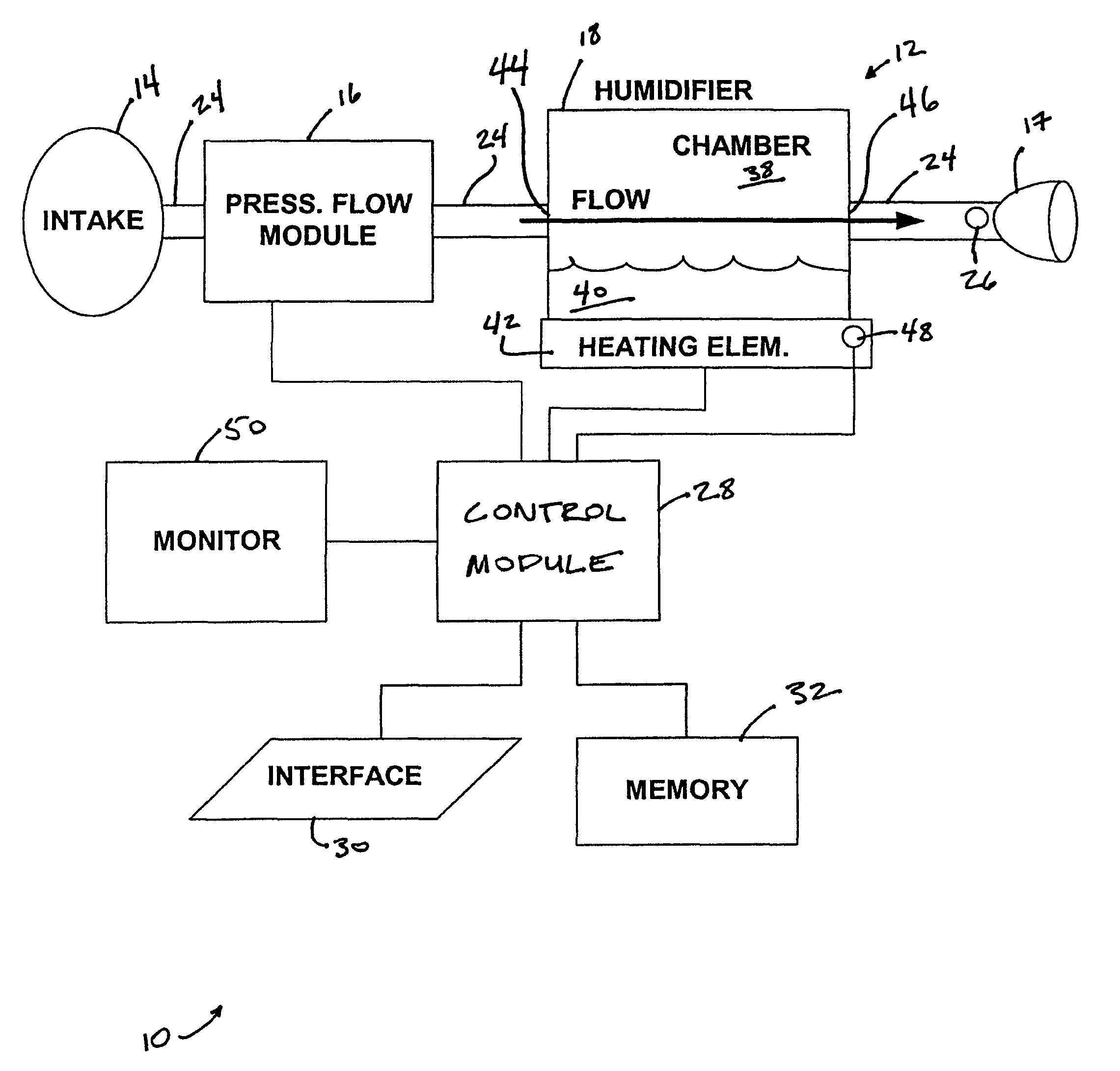
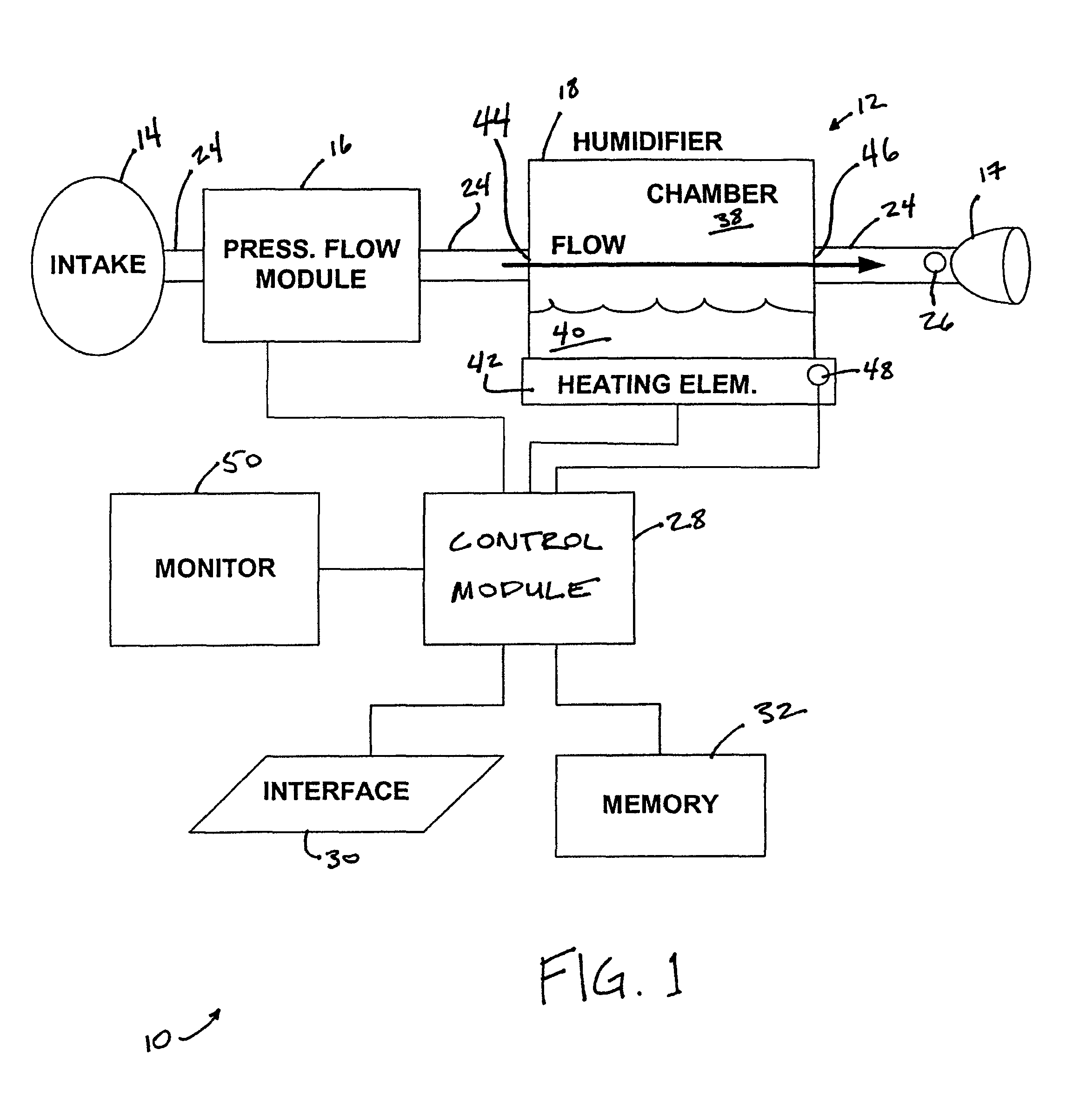
[0019]FIG. 1 schematically illustrates an exemplary embodiment of a patient treatment system 10 according to the principles of the present invention. Patient treatment system 10 is capable of providing breathable gas to a patient while automatically controlling the pressure of the breathable gas according to a predetermined mode of ventilation. Patient treatment system 10 includes a patient circuit 12 that provides the breathable gas to the patient from a gas source.

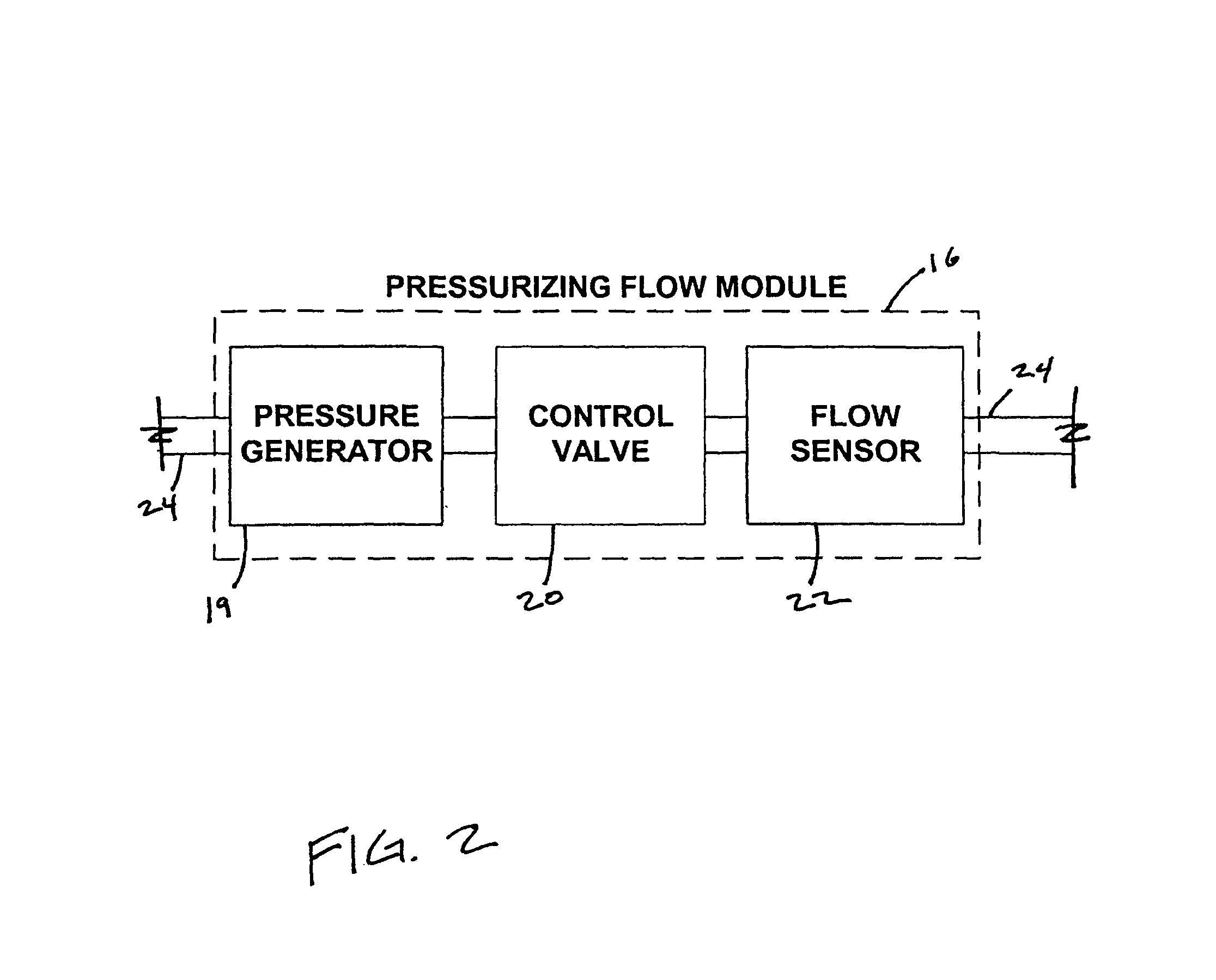
[0020]In one embodiment, the gas source is ambient air, but may be other types of sources, as will be described later. The breathable gas is introduced into circuit 12 from the gas source at an intake 14. Intake 14 may include a port, a vent, or an opening. In some embodiments, intake 14 may include a filter that filters the breathable gas as it is introduced into circuit 12. As shown in FIG. 1, a pressurizing flow module 16 controls the pressure and flow of the gas in circuit 12 from intake 14 to a patient interface 17 ...


PUM


Abstract

A patient treatment system and method comprising a patient circuit, a pressurizing flow module disposed in the patient circuit, a humidifier disposed in the patient circuit, a monitor, sensors within the patient circuit, and a processor. The patient circuit delivers a flow of gas from a gas source to an airway of a patient. The pressurizing flow module elevates the pressure of the gas within the patient circuit. The humidifier elevates the humidity of the gas in the patient circuit to a circuit humidity level. The monitor monitors at least one parameter of the gas from the gas source. The sensors generate corresponding signals that can be processed to estimate a rate at which vapor is added to the gas in the patient circuit. The processor determines the humidity level of the gas in the patient circuit downstream from the humidifier based on the signals generated by the sensors and the at least one parameter of the gas in the gas source.

Description

CROSS-REFERENCE TO RELATED APPLICATIONS[0001]This application claims priority under 35 U.S.C. §119(e) from provisional U.S. patent application No. 60 / 697,130 filed Jul. 7, 2005 the contents of which are incorporated herein by reference.BACKGROUND OF THE INVENTION[0002]1. Field of the Invention[0003]The invention relates to respiratory treatment systems, and, in particular, to a system and method of humidifying gas in a respiratory treatment system based on the ambient conditions.[0004]2. Description of the Related Art[0005]Humidifiers are commonly used with ventilators, pressure support systems, and other respiratory devices to add humidity to the gas being supplied to a patient via a patient circuit. The humidity added to the gas supplied to the patient by a conventional ventilator or pressure support system is typically monitored and / or controlled in a feedback loop to provide a consistent humidity level. Typically, the humidity has been monitored by placing a temperature and / or h...

Claims


Application Information

Patent Timeline
Patent Type & Authority Patents(United States)
IPC IPC(8): A61M16/16A61M16/00
CPCA61M16/16A61M2016/161A61M2230/432A61M16/0051A61M16/0066A61M2016/0021A61M2205/502A61M2205/3375A61M2205/3365A61M2016/0039A61M2016/0069A61M2016/109A61M2016/0027A61M2205/3368A61M16/1075A61M2016/103A61M2205/80A61M2016/202A61M16/202A61M16/161A61M16/109A61M16/0069A61M16/024
Inventor PUJOL, J. RAYMONDPERROZ, JR., WILLIAMRYBICKI, ROBERT G.
Owner PHILIPS RS NORTH AMERICA LLC
Why Eureka
Try Eureka