Flow baffle installation methods and apparatus

a technology of installation methods and flow baffles, applied in the direction of liquid displacement, separation processes, water treatment water nature, etc., can solve the problems of affecting the removal of particles from water, and difficulty in retrofitting an existing sump

Active Publication Date: 2014-03-04
UPSTREAM TECH
View PDF10 Cites 16 Cited by
  • Summary
  • Abstract
  • Description
  • Claims
  • Application Information

AI Technical Summary

Problems solved by technology

However, large flows through the sump may re-entrain the particles before the particles are removed from the sump.
Furthermore, the flow velocities and flow patterns in the sump may hinder the removal of particles from the water by settling.
These existing sumps, in various aspects, may be a generally confined space with limited access through a manhole or other such entryway.
The confined space with limited access may cause difficulty with retrofitting an existing sump with such apparatuses to control the flow.

Method used


Image

  • Flow baffle installation methods and apparatus
  • Flow baffle installation methods and apparatus
  • Flow baffle installation methods and apparatus

Examples


Embodiment Construction

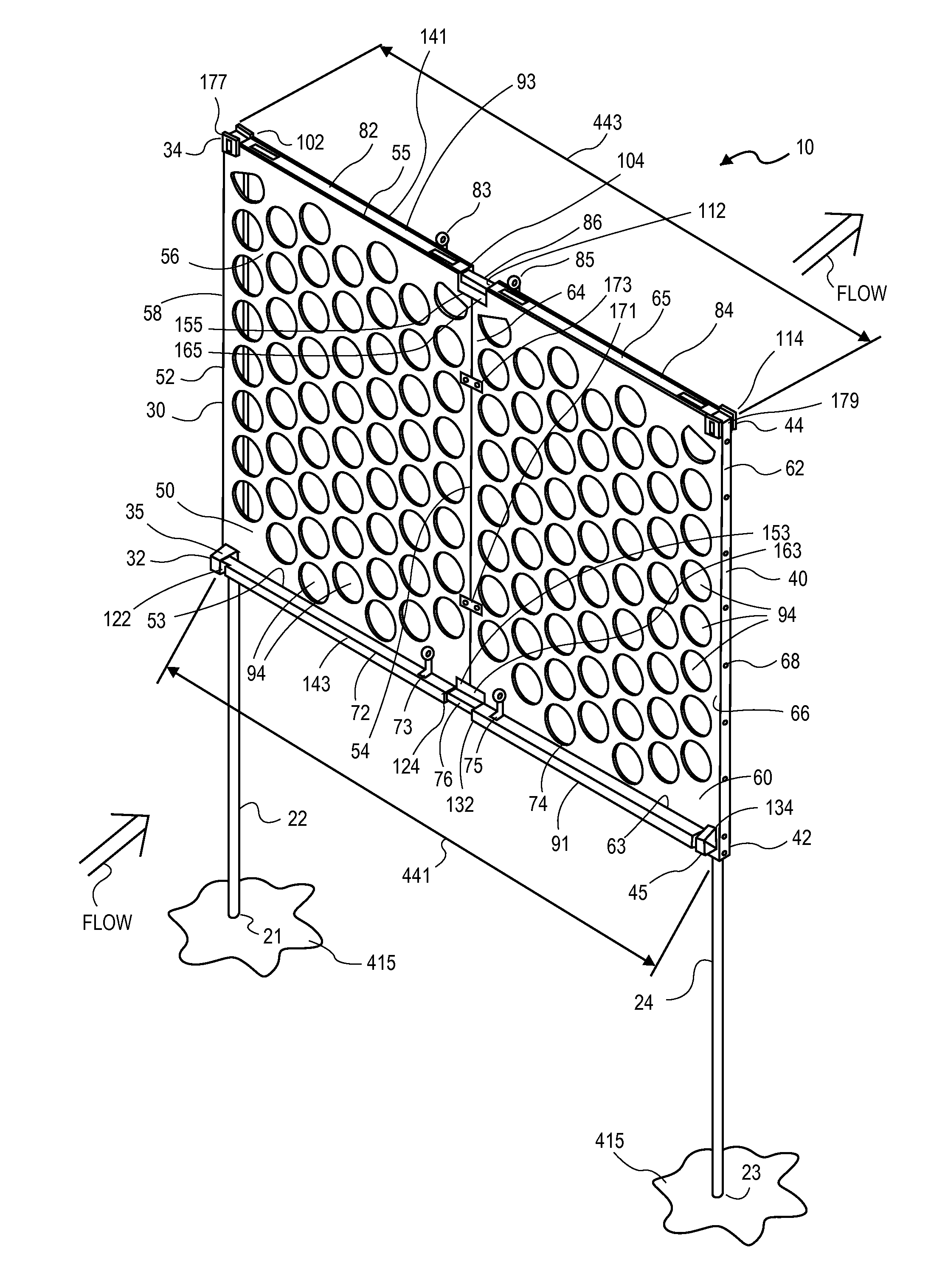
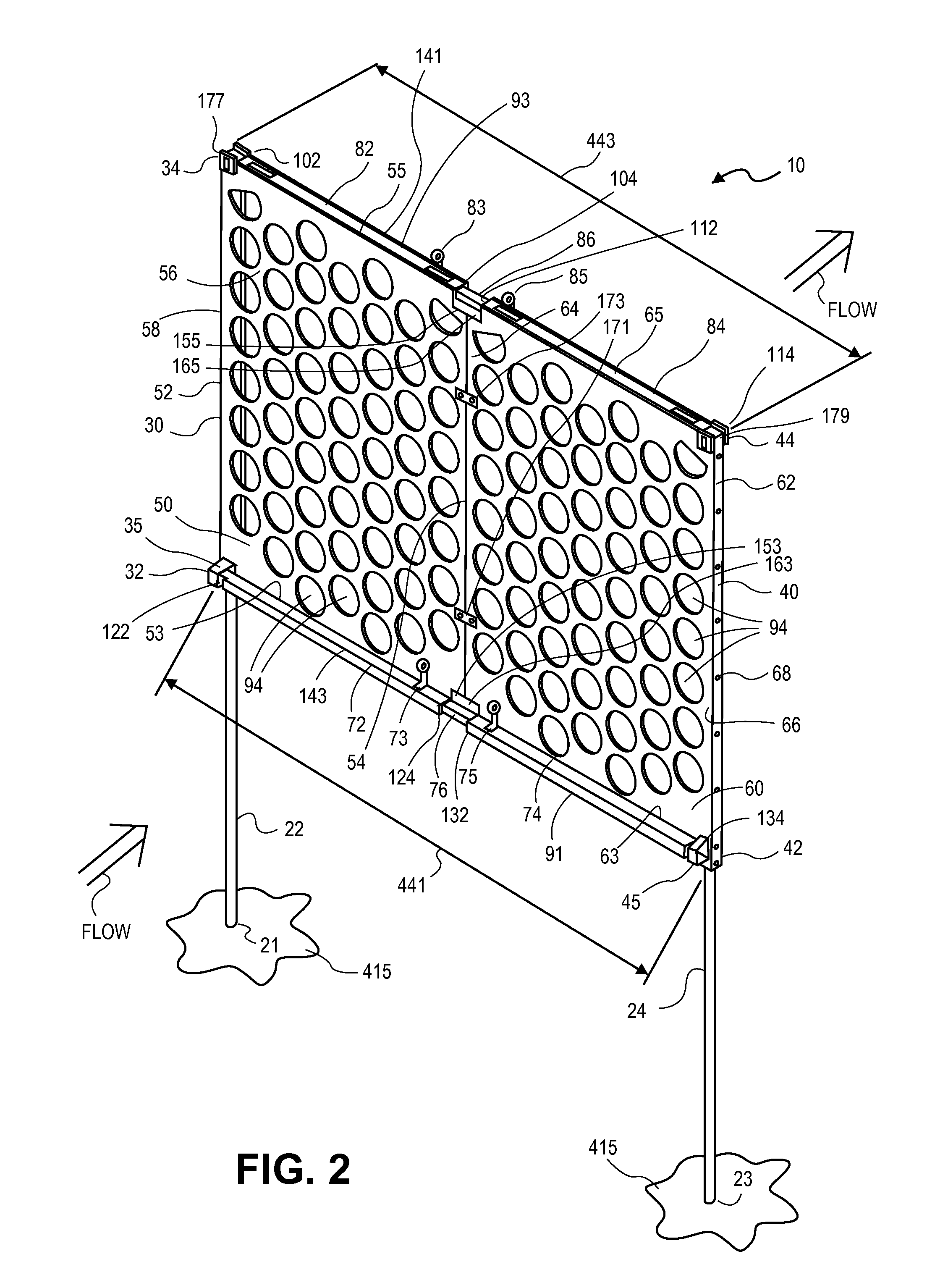
[0025]Methods of flow baffle apparatus installation along with associated flow baffle apparatus and kits are disclosed herein. The flow baffle apparatus may be positioned within a sump in order to train the flow within the sump, and the flow baffle apparatus may be formed for that purpose. The flow baffle apparatus may be secured to the walls of the sump in ways that may account for irregularities in the walls. The sump may be accessed through a manhole, and the methods of flow baffle apparatus installation, along with the associated flow baffle apparatus and kits, are designed to be implemented through manhole access, in various aspects.

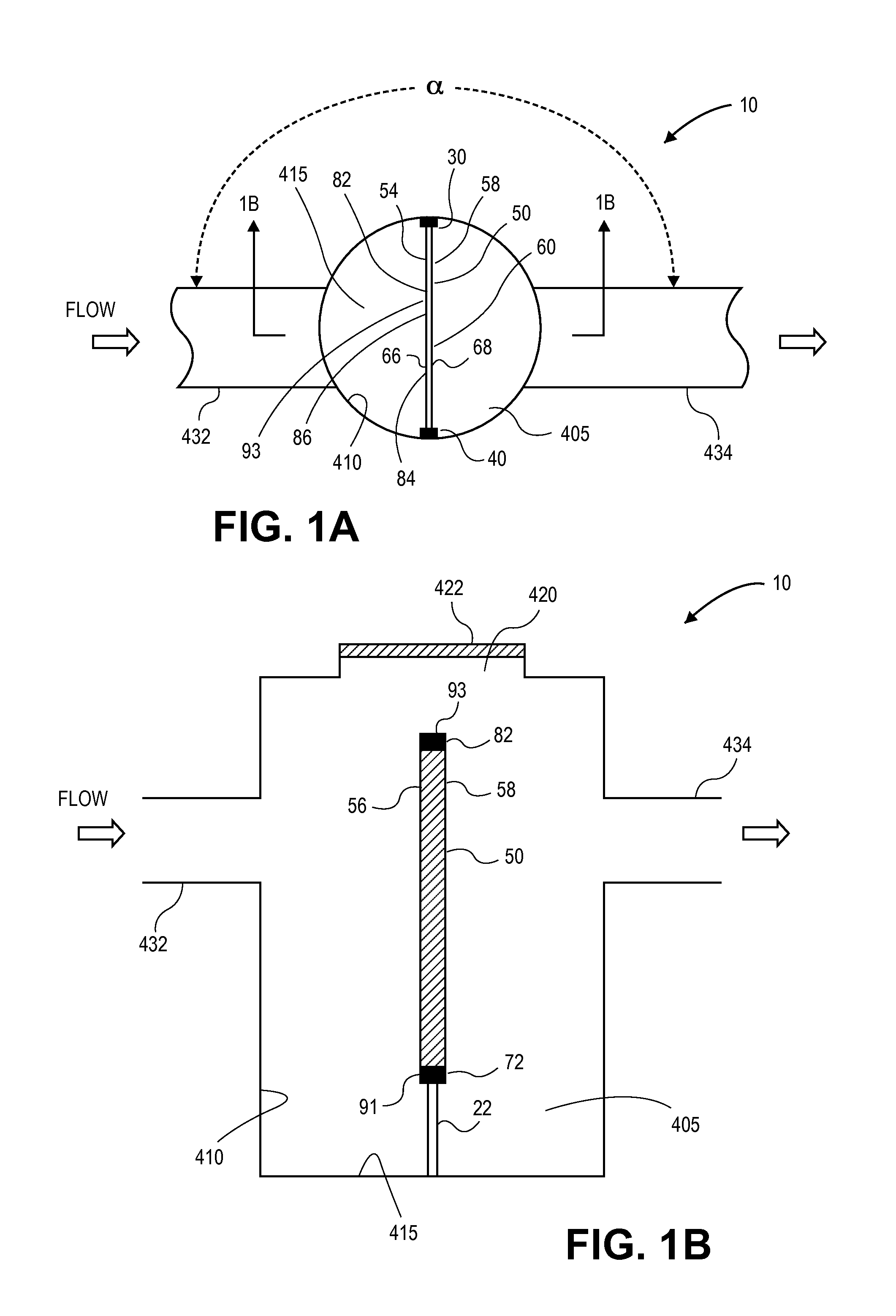
[0026]FIG. 1A illustrates an implementation of flow baffle apparatus 10. As illustrated in FIG. 1A, flow baffle apparatus 10 is positioned in sump 405 to train the flow therein. Pipe 432 leads into sump 410 and pipe 434 leads from sump 410 so that flow may pass through pipe 432 into sump 410, pass about baffle apparatus 10, which is positioned withi...


PUM

PropertyMeasurementUnit
diameteraaaaaaaaaa
diameteraaaaaaaaaa
diameteraaaaaaaaaa

Abstract

A method of flow baffle installation is disclosed herein. The method, in various aspects includes the steps of orienting a side support at a specified elevation about a sidewall of a sump using a leveling support, bolting the side support to the sidewall of the sump following the step of orienting a side support at a specified elevation about a sidewall of a sump using a leveling support, orienting an opposing side support at the specified elevation about the sidewall of the sump using a corresponding leveling support, bolting the opposing side support to the sidewall of the sump following the step of orienting an opposing side support at the specified elevation about the sidewall of the sump using a corresponding leveling support, adjusting an adjustable cross-member to span between the side support and the opposing side support. This Abstract is presented to meet requirements of 37 C.F.R. §1.72(b) only. This Abstract is not intended to identify key elements of the apparatus and methods disclosed herein or to delineate the scope thereof.

Description

BACKGROUND OF THE INVENTION[0001]1. Field[0002]The apparatus, methods, and kits disclosed herein related to retrofit sumps to control the flow therein.[0003]2. Background[0004]Water such as, for example, storm water, sanitary wastewater, and other such flows may contain pollutants in the form of various settleable particulates. In various aspects, the water may be channeled through various existing pipes or other drainage channels that pass through one or more sumps. In order to control pollution, it may be desirable to utilize these existing sumps to capture particulates entrained in the water.[0005]The flow velocity may decrease as the water passes through the sump, so that some of the particles entrained in the water may settle to the bottom of the sump. The particles settled to the bottom of the sump may be retained at the bottom of the sump, and may be removed from the bottom of the sump by periodic cleaning. However, large flows through the sump may re-entrain the particles be...

Claims


Application Information

Patent Timeline
Patent Type & Authority Patents(United States)
IPC IPC(8): E03F5/14C02F103/00
CPCC02F2307/08C02F1/52B01D2221/12C02F2103/001E03F5/14B01D21/0033B01D21/0003C02F2201/002Y10T137/0402Y10T137/598
Inventor BRAUNWARTH, WILLIAM F.BREWER, BONNIEGENDLER, AARON
Owner UPSTREAM TECH
Why Eureka
Try Eureka