Three-dimensional measurement device

a three-dimensional measuring and measurement technology, applied in measurement devices, instruments, surveying and navigation, etc., can solve the problems of large device volume, frequent manipulation of the device, and relatively complex manufacture and use of the device, so as to reduce the aforementioned drawbacks and simplify the design and use.

Inactive Publication Date: 2014-03-25
CELETTE FRANCE
View PDF11 Cites 0 Cited by
  • Summary
  • Abstract
  • Description
  • Claims
  • Application Information

AI Technical Summary

Benefits of technology

[0008]The object of the invention is to propose a three-dimensional measuring device the design of which aims to minimise the aforementioned drawbacks. It thus relates to a measuring device that is of simpler design and use, while being compact.GENERAL DEFINITION OF THE INVENTION
[0015]The device according to the invention allows three-dimensional measurements with remarkable economy of means and saving in space: this is because it uses only a single articulated arm. In addition, because of its very compactness, it is easy to move on the support assembly and, depending on the length of the travel chosen for the telescopic rod, it can adapt to the measurement of points situated at distances, in particular heights, that are very variable with respect to the support assembly: in an application aimed at measurement apparatus on damaged vehicle inspection benches, the measuring device according to the invention adapts to numerous vehicle configurations.

Problems solved by technology

However, it requires, in order to make the measurement, at least two arms articulated on each other, which makes the manufacture and use of the device relatively complex, and makes the device relatively bulky and expensive.
However, it requires frequent manipulation of the device in order to mount and demount the piston rods according in particular to the type of vehicle to be checked.

Method used


Image

  • Three-dimensional measurement device
  • Three-dimensional measurement device
  • Three-dimensional measurement device

Examples


Embodiment Construction

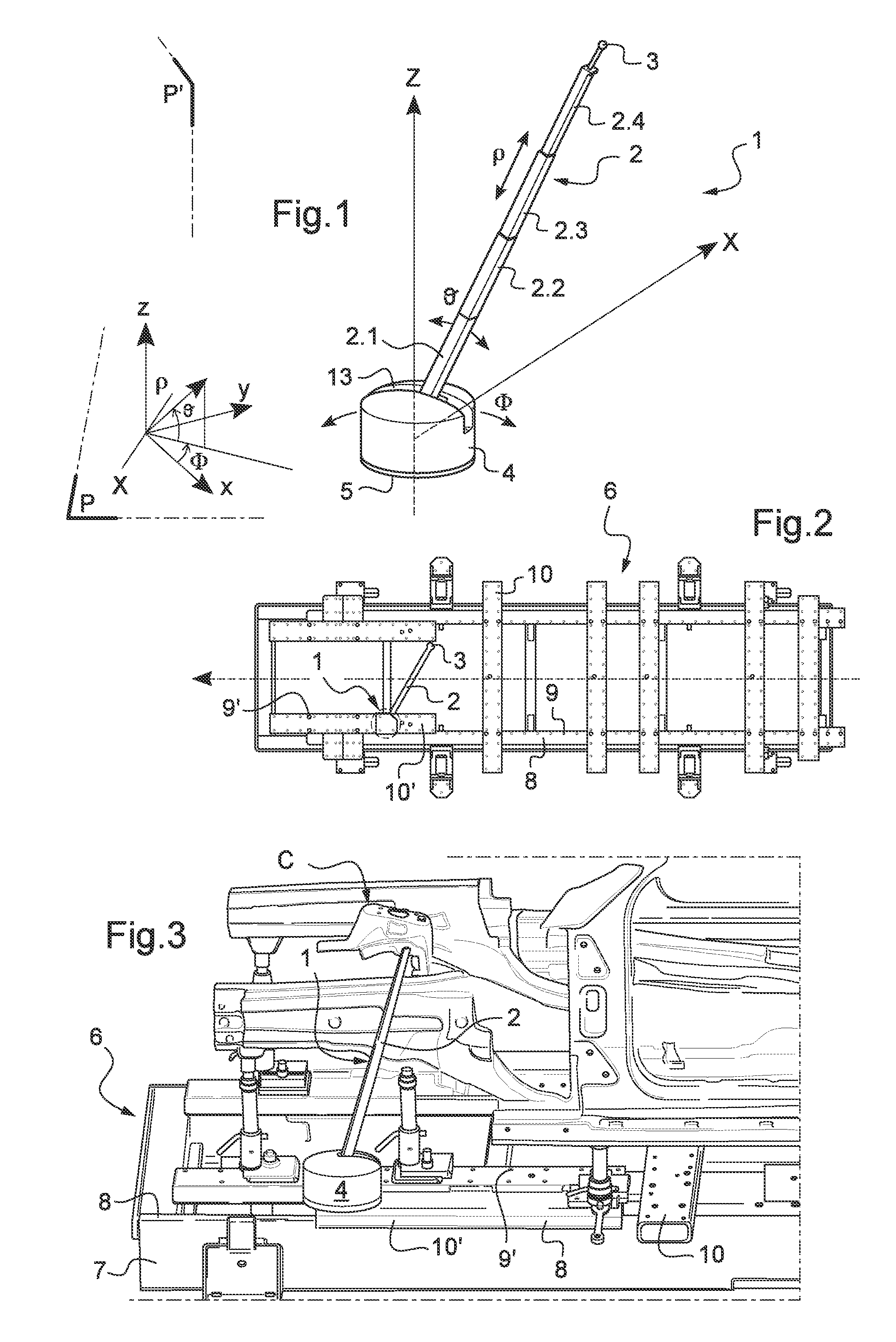
[0026]FIG. 1 shows schematically the measuring device 1 according to the invention intended to be mounted on an inspection bench in order to measure the position of points on components of a vehicle.

[0027]The device is shown in FIG. 1 as disposed once mounted on the inspection bench.

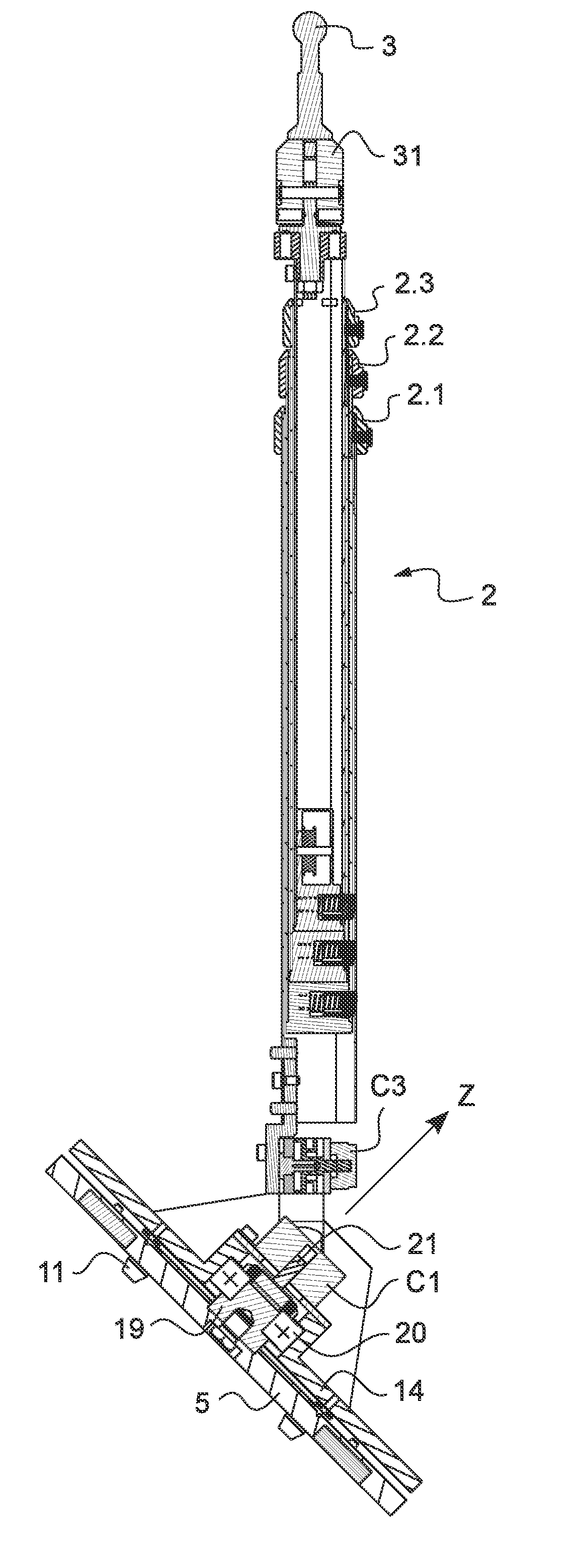
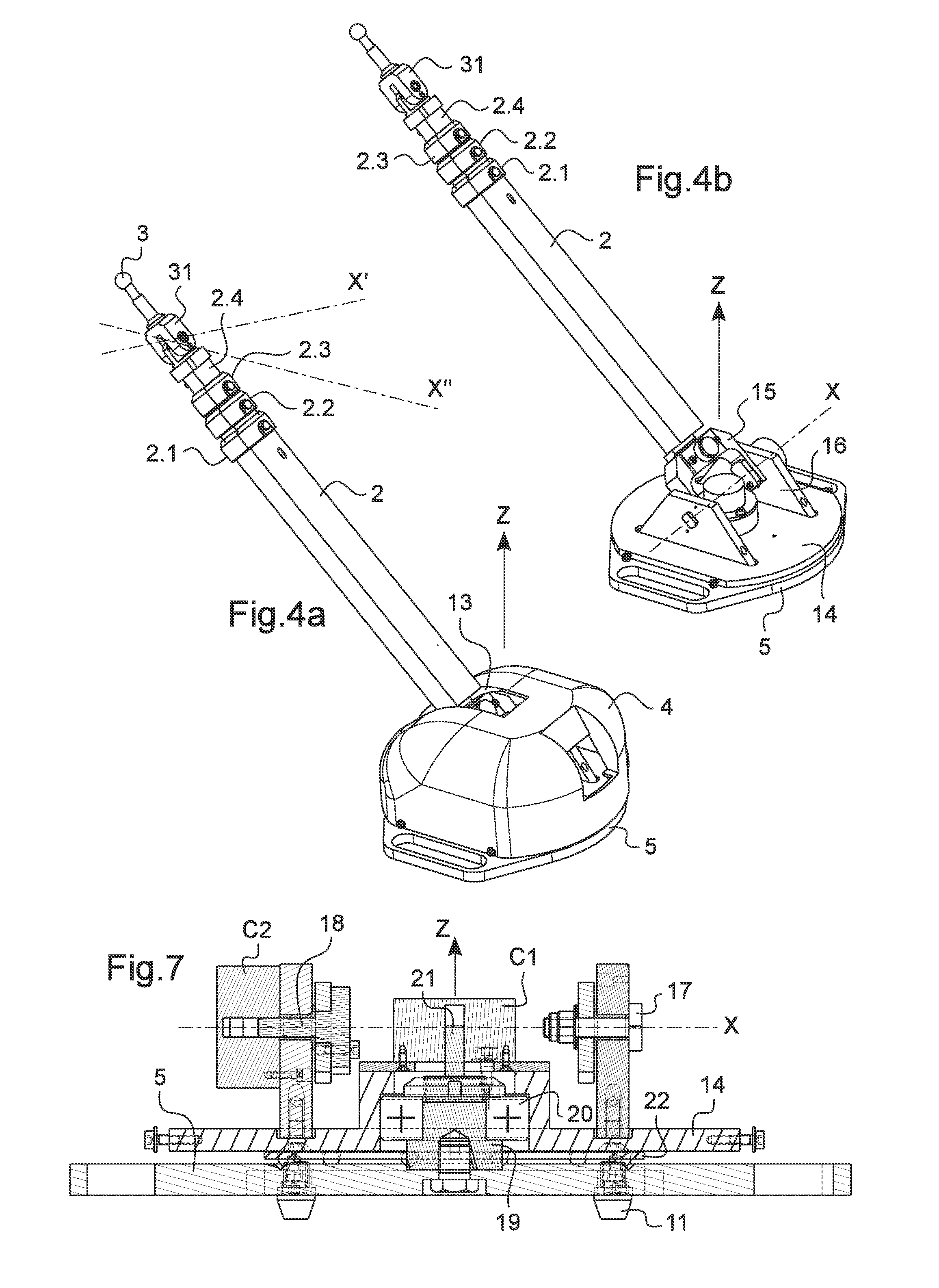
[0028]This device comprises a single telescopic arm 2 mounted by its bottom end on a rotation plate, not visible in this figure since it is disposed under a protective cover 4, this rotating plate being itself mounted on a base 5 intended to be fixed to the inspection bench (elements detailed by means of the following figures).

[0029]The single telescopic arm 2 is provided at its top end with a feeler 3 and, in a known fashion, is composed of several hollow rods 2.1, 2.2, 2.3, 2.4, here for example with a rectangular cross section and sliding in one another. In this example they are four in number and are shown in their maximum deployed position. The feeler 3, in a known fashion, is in the form of a spher...


PUM


Abstract

The invention concerns a three-dimensional measuring device, which comprises:a base (5) intended to be fixed to a support assembly (6) and lying in a first plane,a plate (14) mounted so as to rotate on the base (5) about a first axis (Z), said plate being equipped with a first sensor (c1) determining the angle of rotation (Φ) of the plate about this first axis (Z),a single rocking telescopic arm (2), a first end of which is articulated on the plate (14) about a second axis (X) orthogonal to the first axis (Z), the angle of rotation (θ) of said arm about the second axis (X) being determined by a second sensor (c2), the second end of the single telescopic arm being provided with a measuring feeler (3), and the said single arm being equipped with a third sensor (c3) determining the elongation length (ρ) of the arm in translation, so that the spatial position of the measuring feeler is determined by its polar coordinates (ρ, θ, Φ) in the fixed three-dimensional reference frame consisting of the base (5) once the latter is fixed to the support assembly (6).

Description

CROSS REFERENCE TO RELATED APPLICATIONS[0001]This application is a National Stage of International Application No. PCT / EP2010 / 056742, filed on May 17, 2010, which claims priority from French Patent Application No. 0902420, filed on May 19, 2009, the contents of all of which are incorporated herein by reference in their entirety.FIELD OF THE INVENTION[0002]The present invention concerns a three-dimensional measuring device.BACKGROUND OF THE INVENTION[0003]Numerous three-dimensional measuring devices exist in varied fields of use. By way of non-limitative illustration, the invention will concern more particularly the use of this type of measuring device for checking deformations in a damaged vehicle body.[0004]A first known type of three-dimensional measuring device uses a plurality of articulated arms that each comprise angular sensors integrated so as to determine the rotation angles of the arms about each of their articulation axes provided. A measuring device of this type is thus ...

Claims


Application Information

Patent Timeline
Patent Type & Authority Patents(United States)
IPC IPC(8): G01B5/008
CPCG01B5/008G01B5/0025
Inventor JOURDAN, STEPHANE
Owner CELETTE FRANCE
Why Eureka
Try Eureka