
Three-dimensional measurement device
a three-dimensional measuring and measuring device technology, applied in the direction of measuring devices, instruments, using mechanical means, etc., can solve the problems of large device volume, frequent manipulation of the device, and relatively complex manufacture and use of the device, so as to reduce the aforementioned drawbacks and simplify the design and use.
- Summary
- Abstract
- Description
- Claims
- Application Information
AI Technical Summary
Benefits of technology
Problems solved by technology
Method used
Image

Examples
Embodiment Construction
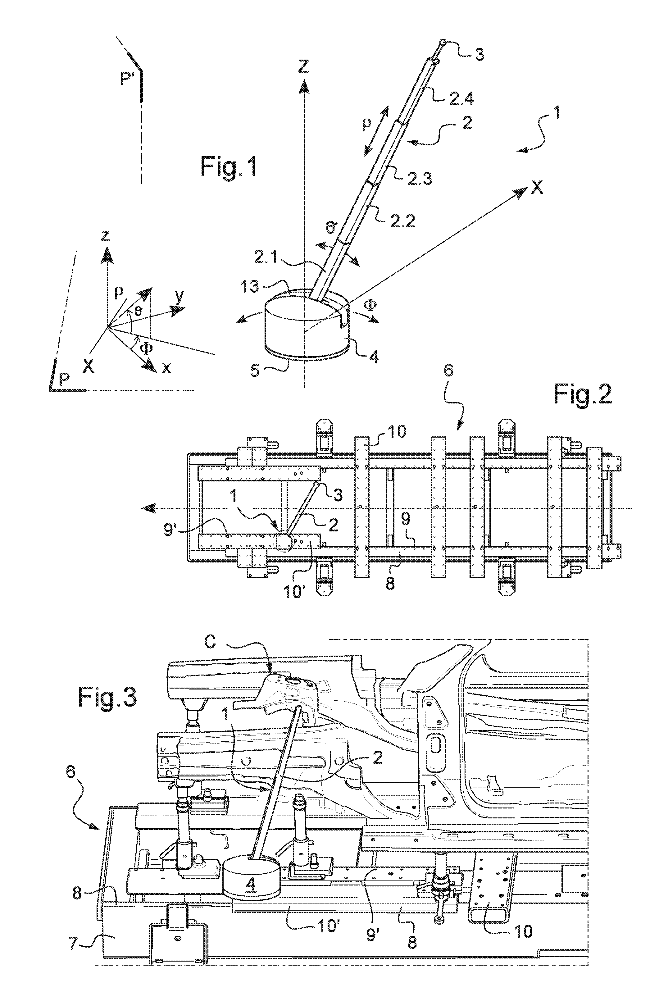
[0025]FIG. 1 shows schematically the measuring device 1 according to the invention intended to be mounted on an inspection bench in order to measure the position of points on components of a vehicle.
[0026]The device is shown in FIG. 1 as disposed once mounted on the inspection bench.
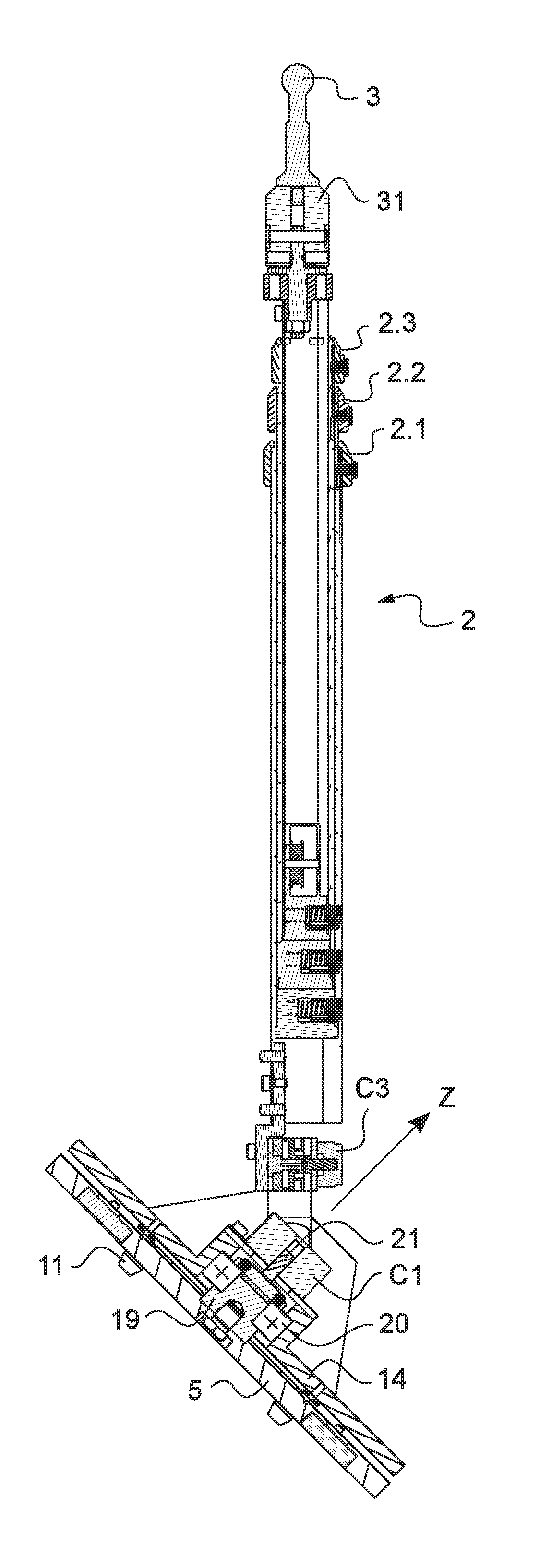
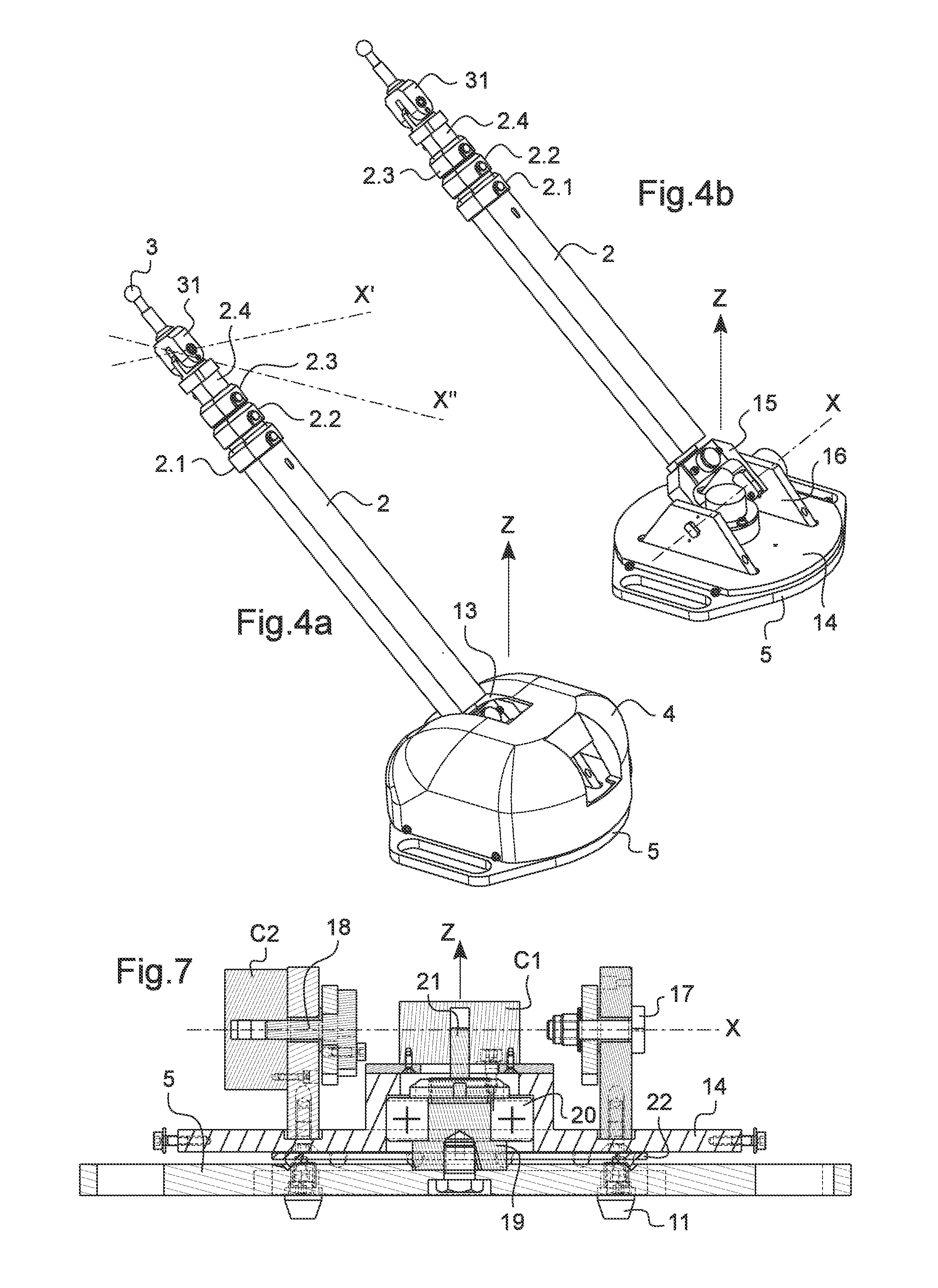
[0027]This device comprises a single telescopic arm 2 mounted by its bottom end on a rotation plate, not visible in this figure since it is disposed under a protective cover 4, this rotating plate being itself mounted on a base 5 intended to be fixed to the inspection bench (elements detailed by means of the following figures).
[0028]The single telescopic arm 2 is provided at its top end with a feeler 3 and, in a known fashion, is composed of several hollow rods 2.1, 2.2, 2.3, 2.4, here for example with a rectangular cross section and sliding in one another. In this example they are four in number and are shown in their maximum deployed position. The feeler 3, in a known fashion, is in the form of a spher...
PUM
 Abstract
Description
Claims
Application Information