Camshaft adjuster, in particular with camshaft

a camshaft and camshaft technology, applied in the direction of valve arrangement, yielding coupling, coupling, etc., can solve the problems of long extended camshafts prone to jamming and sticking, and achieve the effect of less mass

Inactive Publication Date: 2014-03-25
HILITE GERMANY
View PDF51 Cites 4 Cited by
  • Summary
  • Abstract
  • Description
  • Claims
  • Application Information

AI Technical Summary

Benefits of technology

[0024]In accordance with an example embodiment of the present invention, the valve train comprises a double camshaft with an inner camshaft and an outer camshaft. The two camshafts are preferably designed coaxially. By means of a rotatory change in position of the inner camshaft to the outer camshaft, the angular position of at least one cam of the inner camshaft is adjusted or set relative to a cam or the outer camshaft. Advantageously, the cam of the inner camshaft is mounted on the outer camshaft, bound by means of a pin to the inner camshaft, so that it can pivot. The larger bearing surface of the outer camshaft can be utilized, while the event position of the valve train is made possible by an adjustment of the inner camshaft that possesses less mass.
[0025]The valve train can be adjusted variably to a reference shaft. The valve train comprises at least two camshafts. The valve train has at least one first camshaft and one second camshaft. The camshafts are disposed in .such a way that two of the camshafts are present as a coaxially configured double camshaft. The double camshaft is observed from the outside as a unified camshaft, the cams of which can be adjusted differently. The cams are divided into sets, which can occupy cam positions that are variable relative to one another. There is a camshaft adjuster for this purpose. The camshaft adjuster is preferably a pivoting-rotor camshaft adjuster. The camshaft adjuster is attached by its center to one of the two camshafts with a first set of rotatable components by a connection means that passes through the center of the camshaft adjuster and engages to a first (inner) of the two camshafts, the connection means comprising one of a screw or a central valve. The camshaft adjuster has different sets of components that are rotatable relative to one another, such as a rotor with vanes, at least one locking pin and oil conducting channels. A maximum radius is formed by a rim-type mounting flange to the second (outer) camshaft. There is at least one additional connecting means inside the radius that passes through the camshaft adjuster and engages the mounting flange. This additional connection means can be a screw. Ideally, there are several of such additional connection means that pass through and engage the mounting flange of the second camshaft second set of rotatable components of the camshaft adjuster. One part of the camshaft adjuster is rotatory concurrently with the first camshaft. The other part of the camshaft adjuster is rotatory concurrently with the second camshaft. A double camshaft can be conveniently, reliably and rapidly connected to a suitable camshaft adjuster in this manner.
[0030]The additional one or more connection means that pass through the camshaft adjuster and engage with the mounting flange is or are located within a radius. The imaginary radius or radius to be formed runs inside the camshaft adjuster. The radius is also disposed centrally around the central fastening means. The radius is smaller than the inner wall of the stator. In one example embodiment, the radius may be as small as possible, e.g., at a maximum, as large as the rotor core. All connection means are found in the center of the camshaft adjuster. The inertia of the camshaft adjuster is reduced in this way.

Problems solved by technology

It has been shown, especially for double camshafts, that very long extended camshafts tend toward jamming and sticking.

Method used


Image

  • Camshaft adjuster, in particular with camshaft
  • Camshaft adjuster, in particular with camshaft
  • Camshaft adjuster, in particular with camshaft

Examples


Embodiment Construction

[0048]The ensuing detailed description provides exemplary embodiments only, and is not intended to limit the scope, applicability, or configuration of the invention. Rather, the ensuing detailed description of the exemplary embodiments will provide those skilled in the art with an enabling description for implementing an embodiment of the invention. It should be understood that various changes may be made in the function and arrangement of elements without departing from the spirit and scope of the invention as set forth in the appended claims.

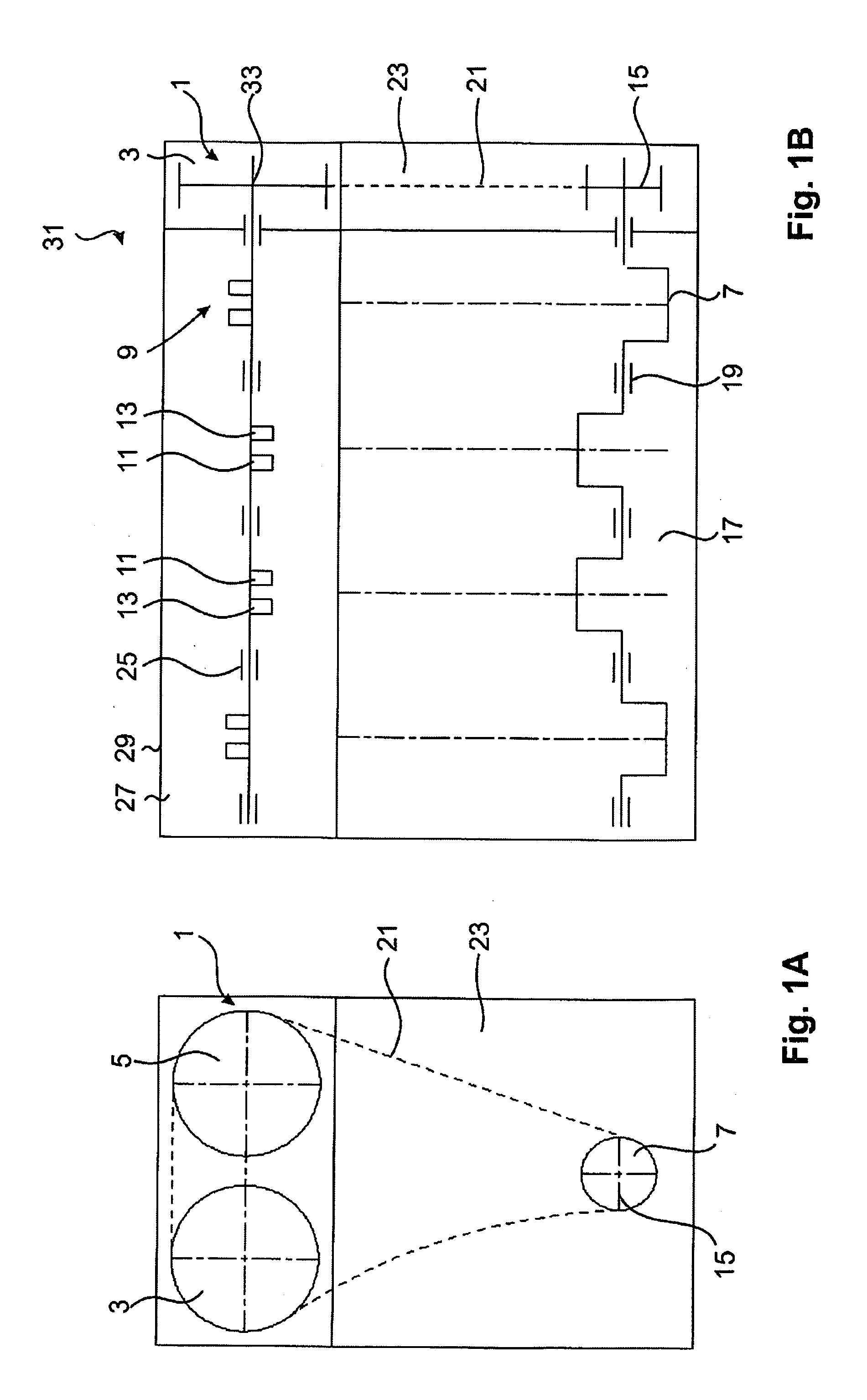
[0049]FIG. 1A shows the schematically presented open chain case 23, in which the driven means 21, i.e., the chain, assures a drive-type connection between a reference shaft 7 and at least one of the camshaft adjusters 3, 5. The camshaft adjuster 3 is part of the valve train 1. The camshaft adjuster 5 is also part of the valve train 1. The driven means 21 is engaged on reference shaft 7 and a flywheel 15 is present also on reference shaft 7 for...


PUM


Abstract

A valve train comprises a double camshaft with an inner camshaft and an outer camshaft. The two camshafts are preferably designed coaxially. By means of a rotatory change in position of the inner camshaft to the outer camshaft, the angular position of at least one cam of the inner camshaft is adjusted or set relative to a cam of the outer camshaft. The cams are divided into sets that can occupy variable cam positions relative to one another. Various configurations of a camshaft adjuster are provided for this purpose.

Description

[0001]This application claims the benefit of German patent application number DE 10 2010 033 296.8 filed on Aug. 4, 2010, which is incorporated herein by reference in its entirety and for all purposes.BACKGROUND OF THE INVENTION[0002]The present invention relates to a valve train of an internal combustion engine with a double camshaft.[0003]A rotary drive that is specifically made for an adjusting shaft of a variable valve train is known from EP 1 347 154 A2 (Applicant: Hydraulik-Ring GmbH; Priority date: Mar. 20, 2003). A first rotatory hydraulic drive is joined to a second rotatory hydraulic drive so that coarse and fine adjustments of an exact cam position within a valve train chain are possible. In other words, the rotary angle position to be adjusted is made possible by a two-stage system.[0004]U.S. Pat. No. 2,911,956 (Applicant: Smith; Date filed: Jan. 7, 1959) describes a plate-type positioner, by means of which a pivoting movement of a first plate influences the pivoting ran...

Claims


Application Information

Patent Timeline
Patent Type & Authority Patents(United States)
IPC IPC(8): F01L1/34
CPCF01L1/3442
Inventor KNECHT, ANDREASBORCHELT, SEBASTIANPOHL, DIRK
Owner HILITE GERMANY
Why Eureka
Try Eureka