
Dual Armature Motor/Generator With Flux Linkage

a technology of electric motors and generators, applied in the direction of windings, mechanical devices, superconductor devices, etc., can solve the problems of “wasted flux” and the inability of machines to produce power at low voltage and high current, so as to increase the overall electrical efficiency, reduce the mass of the machine, and increase the power density

Inactive Publication Date: 2011-06-23
GOODZEIT CARL L +1
View PDF55 Cites 21 Cited by
  • Summary
  • Abstract
  • Description
  • Claims
  • Application Information

AI Technical Summary

Benefits of technology

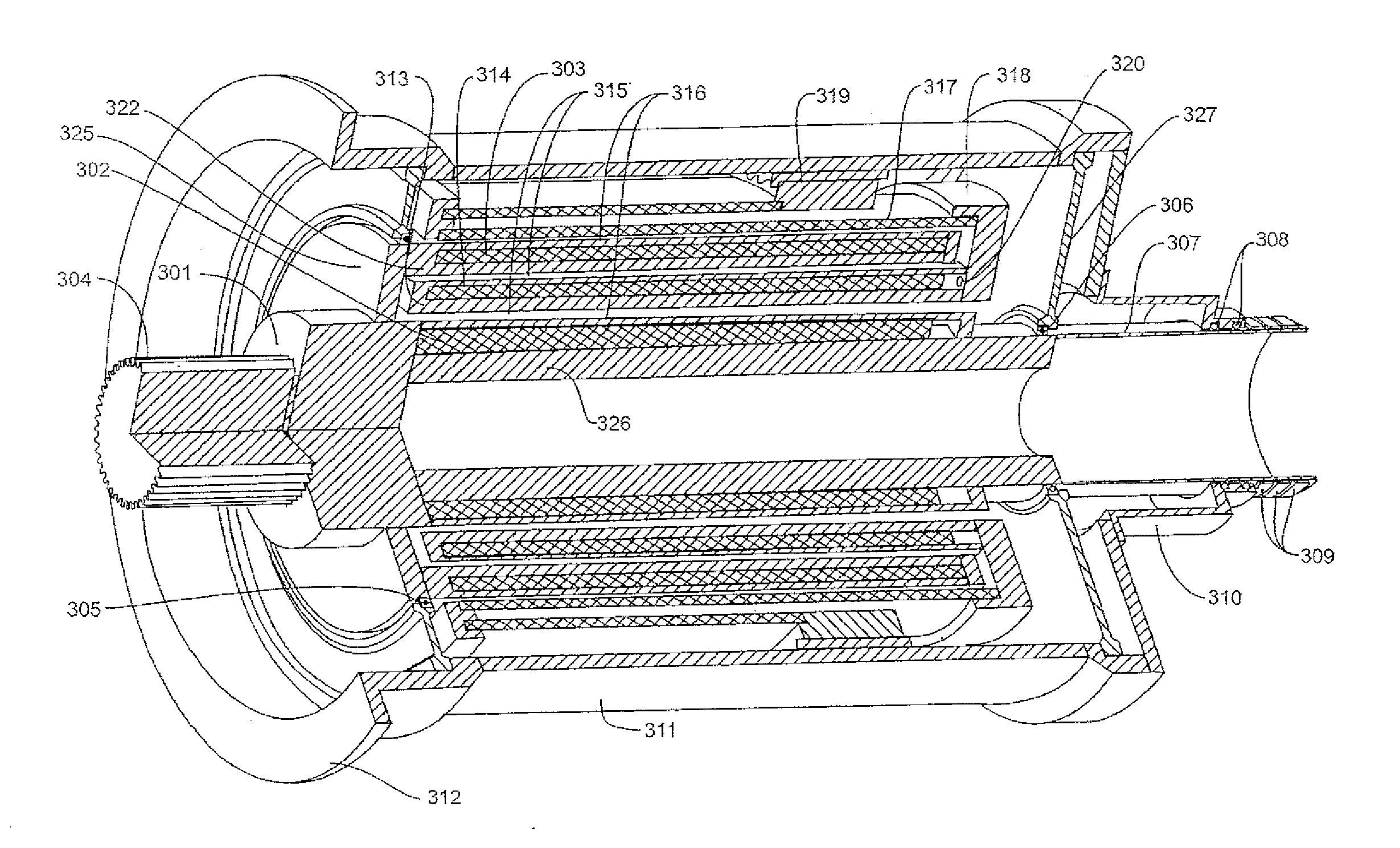
[0015]Relative rotational motion between the field and armature coils can be achieved by having either one be the rotor; the preferred configuration would be for the armature coils to be the rotor. By using two armature coil sections, one inside the field coil aperture and the other external to the field coil, the flux linkage between the armature and superconducting field coil can be approximately doubled. This is a more efficient use of the superconductor. The increased flux linkage in the invented technology produces a substantially higher voltage than can be obtained with current conventional superconducting machine technology.
[0029]A seventh objective is to provide improved electric machines that have a substantially increased power density and thus are more compact and have significantly less mass for the same performance.

Problems solved by technology

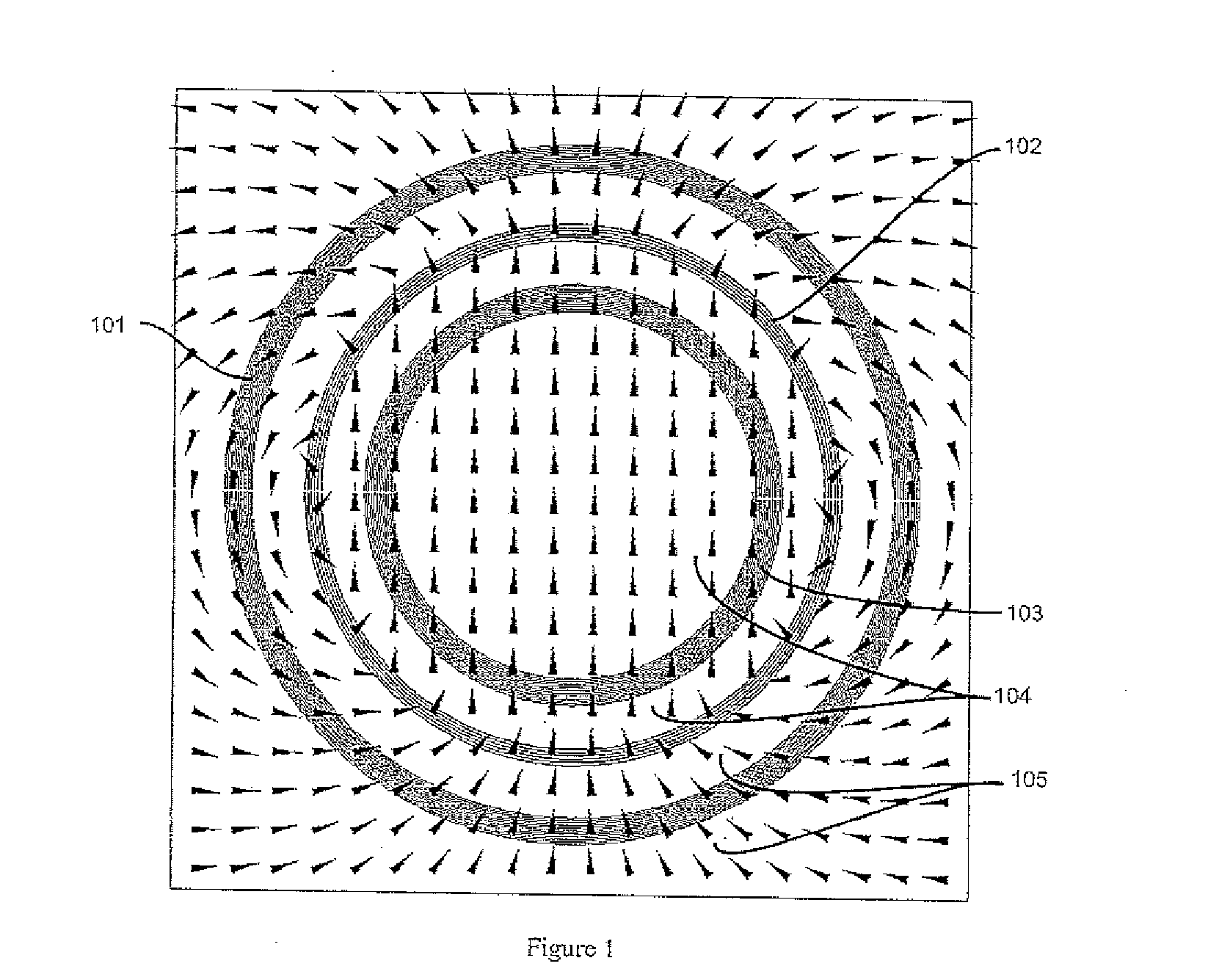
This amounts to “wasted flux” in both cases because the field on the inside of the field coil of the synchronous machine is not linked to the coils of the armature and the field on the outside of the field coil in the “DC type” machine is not linked to the coils of the armature.
In this case there is only one effective current path in the rotor and thus the machine can only produce power at low voltage and high current.

Method used


Image

  • Dual Armature Motor/Generator With Flux Linkage
  • Dual Armature Motor/Generator With Flux Linkage
  • Dual Armature Motor/Generator With Flux Linkage

Examples


Embodiment Construction

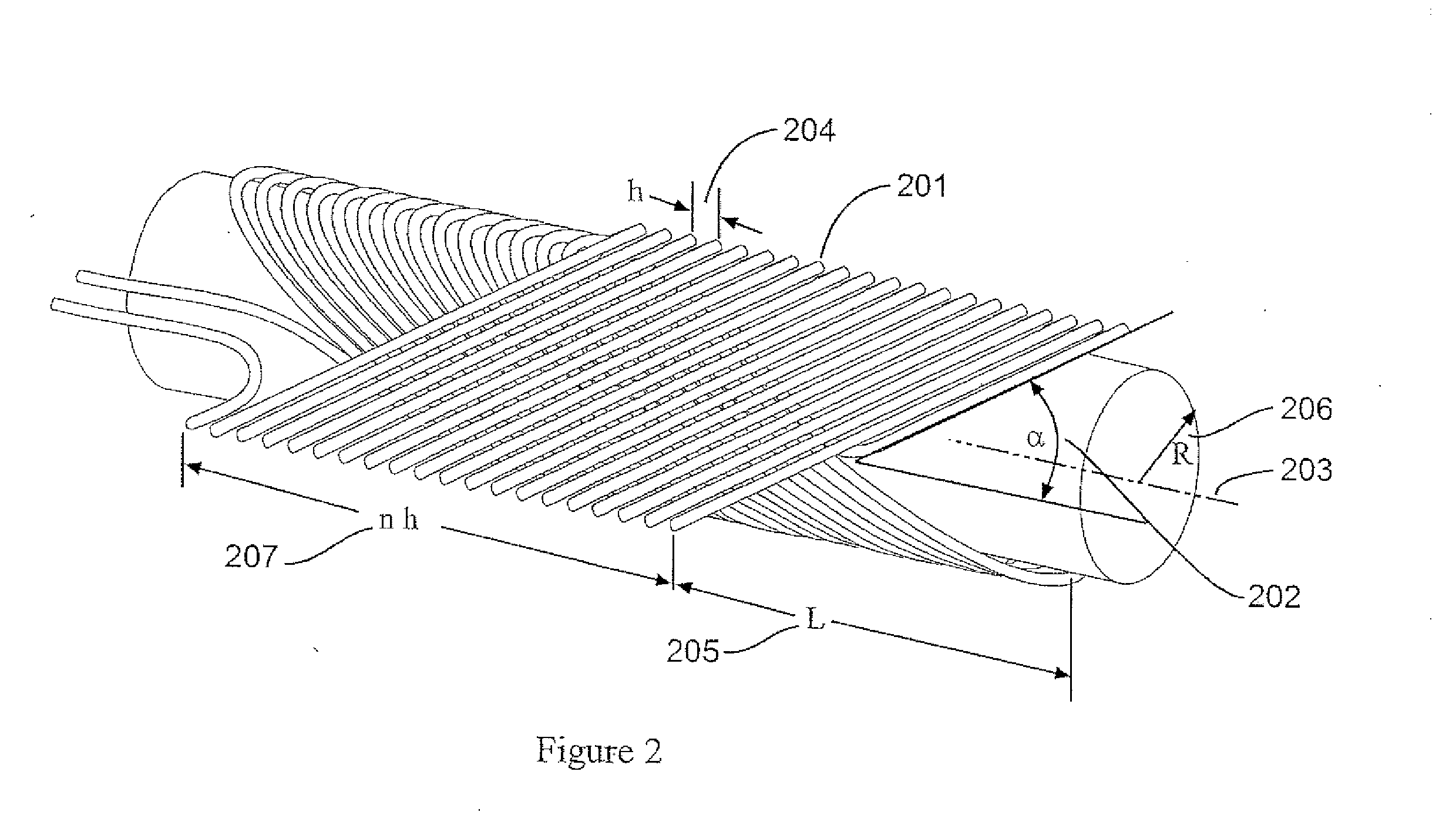
[0037]The preferred embodiment of this invention is a 2-pole machine that contains a rotating armature with three 2-pole coils in each of the two concentric rotor sections, that are placed in an external multi-pole field of order N=2 created by a stationary superconducting field coil. The three armature coils of each rotor section are oriented such that the spatial angles of their magnetic axes are 120° apart and the respective coils in each armature section are connected in series so the generated voltages in the coils of the two sections are added. Other embodiments of this machine can be made with four and more pole configurations for both the rotor and field coils.

[0038]As set forth in the present invention, the armature of a machine consists of two separate sets of coils, one set placed in the aperture of the field source to link flux inside the field source and the other set placed outside the field source to link with the flux external to the field source, which results in ap...


PUM


Abstract

The present invention relates to cylindrical rotating electric machines which comprise armature and field source, with either the field source or the dual armature being the rotating component. The dual armature is composed of two concentric cylindrical sets of coils with the field source situated in the gap between the inner and outer armature sections. Relative rotational motion between the field source and armature coils can be achieved by having either one be the rotor. By using two armature coil sections, one inside the field source aperture and the other external to the field source, the flux linkage between the armature and field source can be approximately doubled. The increased flux linkage in the invented technology produces a substantially higher power density than can be obtained with conventional machine technology.

Description

RELATED APPLICATION DATA[0001]This application is related to Provisional Patent Application Ser. No. 61 / 168,025 filed on Apr. 9, 2009 entitled “Split Rotor Motor / Generator,” and priority is claimed for this earlier filing under 35 U.S.C. §119(e). The Provisional Patent Application is also incorporated by reference into this utility patent application. Further, this is a continuation-in-part application to patent application Ser. No. 12 / 901,836, filed on Oct. 11, 2010, entitled “Dual Armature Motor / Generator With Flux Linkage,” which is a continuation patent application to Ser. No. 12 / 586,103, filed on Sep. 17, 2009 entitled, “Dual Armature Motor / Generator With Flux Linkage Between Dual Armatures And A Superconducting Field Coil,” now U.S. Pat. No. 7,843,094, and priority is claimed for these earlier filings under 35 U.S.C. §120.TECHNICAL FIELD OF THE INVENTION[0002]This invention relates to a dual armature electric motor or generator with flux linkage between the dual armatures and ...

Claims


Application Information

Patent Timeline
IPC IPC(8): H02K21/10H02K16/04
CPCH02K7/1838H02K16/02Y02E40/62H02K55/02Y02E40/622H02K55/00Y02E40/60
Inventor GOODZEIT, CARL L.BALL, MILLICENT J.
Owner GOODZEIT CARL L
Learn More