Turbine wheel for a radial turbine

a technology of radial turbines and turbine wheels, which is applied in the direction of turbines, machines/engines, liquid fuel engines, etc., can solve the problems of complex design of cover disk rotors manufactured from solid blocks, the geometry of turbine wheels that cannot be manufactured, and the inability of milling tools to move into a closed flow chamber, etc., to achieve high rotational symmetry, easy manufacturing, and high solidity

Inactive Publication Date: 2017-04-20
ATLAS COPCO ENERGAS
View PDF6 Cites 19 Cited by
  • Summary
  • Abstract
  • Description
  • Claims
  • Application Information

AI Technical Summary

Benefits of technology

[0023]In an embodiment, the base plate is produced by turning a forged circular blank. Forged metal parts have particularly high solidity and are easily manufactured in simple basic shapes. Due to the turning, a high rotational symmetry of the main body of the base plate is achieved. In this manner, the base plate can be prefabricated particularly easily and favorably in conventional ways.

Problems solved by technology

In this case, however, limitations result with regard to the geometry of the turbine wheel that can be manufactured.
For instance, milling tools cannot move into a closed flow chamber to any possible depth and maneuver therein.
This rules out complex designs for cover disk rotors manufactured from a solid block, in particular in the case of small turbine wheels.
This retrofitting is highly disadvantageous, however, due to the high notch effect and the material weakening which results when the cover disk is joined.

Method used


Image

  • Turbine wheel for a radial turbine
  • Turbine wheel for a radial turbine
  • Turbine wheel for a radial turbine

Examples


Embodiment Construction

[0031]The following is a detailed description of example embodiments of the invention depicted in the accompanying drawings. The example embodiments are presented in such detail as to clearly communicate the invention and are designed to make such embodiments obvious to a person of ordinary skill in the art. However, the amount of detail offered is not intended to limit the anticipated variations of embodiments; on the contrary, the intention is to cover all modifications, equivalents, and alternatives falling within the spirit and scope of the present invention, as defined by the appended claims.

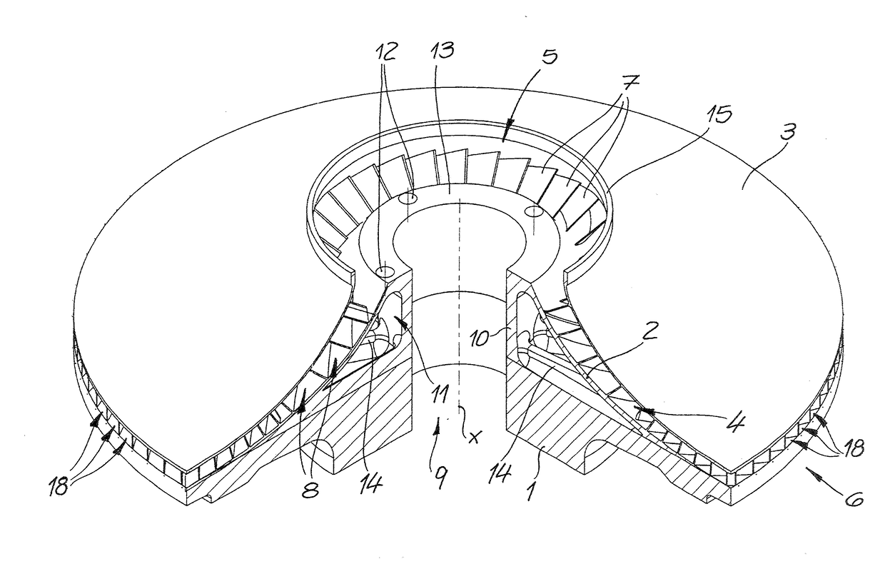
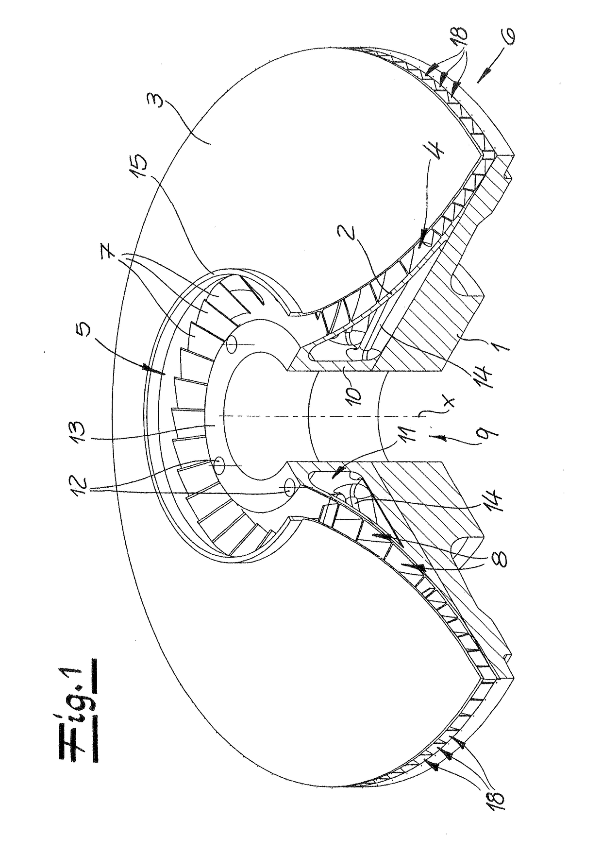
[0032]FIG. 1 depicts a turbine wheel constructed according to the invention. The FIG. 1 turbine wheel comprises a base plate 1, which has rotational symmetry about an axis of rotation x. Situated thereon is a flow chamber 4, which is delimited by a hub disk 2 and a cover disk 3. This flow chamber connects an axial inner opening 5 to a radial, circumferential, outer opening 6 of the turbine ...


PUM

PropertyMeasurementUnit
angleaaaaaaaaaa
angleaaaaaaaaaa
power transmissionaaaaaaaaaa

Abstract

A turbine wheel for a radial turbine includes a rotationally symmetrical base plate and a flow chamber delimited by a hub disk and a cover disk, wherein the flow chamber connects an axial inner opening to a radial outer opening and is subdivided by turbine blades into flow channels. In a method for producing such a turbine wheel, the hub disk, the turbine blades and the cover disk are integrally formed on the base plate using additive production methods.

Description

CROSS-REFERENCE TO A RELATED APPLICATION[0001]The invention described and claimed hereinbelow is also described in German Patent Application DE 10 2015 117 463.4, filed on Oct. 14, 2015. The German Patent Application, the subject matter of which is incorporated herein by reference, provides the basis for a claim of priority of invention under 35 U.S.C. 119(a)-(d).BACKGROUND OF THE INVENTION[0002]The invention relates to a turbine wheel for a radial turbine including a rotationally symmetrical base plate and a flow chamber, which is delimited by a cover disk and a hub disk and which connects an axial inner opening to a radial outer opening and is subdivided by turbine blades into flow channels. The invention also relates to a method for producing such a turbine wheel.[0003]Closed turbine wheels of this type, i.e., so-called cover disk rotors, have the advantage that the medium guided through the turbine flows through the turbine interior without having to come into contact with the o...

Claims


Application Information

Patent Timeline
Patent Type & Authority Applications(United States)
IPC IPC(8): F01D5/04F01D5/34
CPCF01D5/048F05D2240/30F05D2230/22F01D5/34B23P15/006F04D29/2222F04D29/281F04D29/284F05D2230/234B22F10/28F01D5/043F01D5/14F05D2230/53F05D2210/42B22F5/009B33Y80/00B33Y10/00Y02P10/25B23K26/342
Inventor SCHWARZ, LUKAS
Owner ATLAS COPCO ENERGAS
Why Eureka
Try Eureka