Floating sub tool

a sub-tool and floating technology, applied in the direction of drilling pipes, couplings, mechanical equipment, etc., can solve the problems of increasing thread wear, reducing thread wear, and reducing thread wear,

Active Publication Date: 2014-04-01
NOETIC TECH INC
View PDF12 Cites 5 Cited by
  • Summary
  • Abstract
  • Description
  • Claims
  • Application Information

AI Technical Summary

Problems solved by technology

This procedure necessitates leaving the drill bit underground, but the cost of the drill bit is outweighed by savings in both time and money by not needing to use a separate drill string and withdraw it from the wellbore, and then running casing into the wellbore in a separate operation.
Together with frictional drag, this cushion tends to damp the transmission of drilling vibrations initiated at the drill bit that would otherwise be transmitted upward into the top drive and rig structure, which is not a desirable condition.
This axial tension across the thread interface tends to increase thread wear and can lead to thread damage such as galling.
However, this still typically results in the weight of at least one joint of pipe being carried by threads.
Top drive rigs are now being used not only to assemble drill strings, but also to assemble casing strings and production tubing strings, and the pipe most commonly used for casing and production tubing have less robust threads than typical drill pipe.
Simply pressing a known type of floating cushion sub into new service is not always possible or optimally effective, due to limitations in hoisting capacity of the sub, due to the axial load needing to be further reduced to avoid thread damage, and / or due to the need or desire to expedite make-up and break-out by not requiring the vertical position of the top drive to be adjusted as frequently or with as much precision as might otherwise be required.

Method used


Image

  • Floating sub tool
  • Floating sub tool
  • Floating sub tool

Examples


first embodiment

Floating Sub Tool—First Embodiment

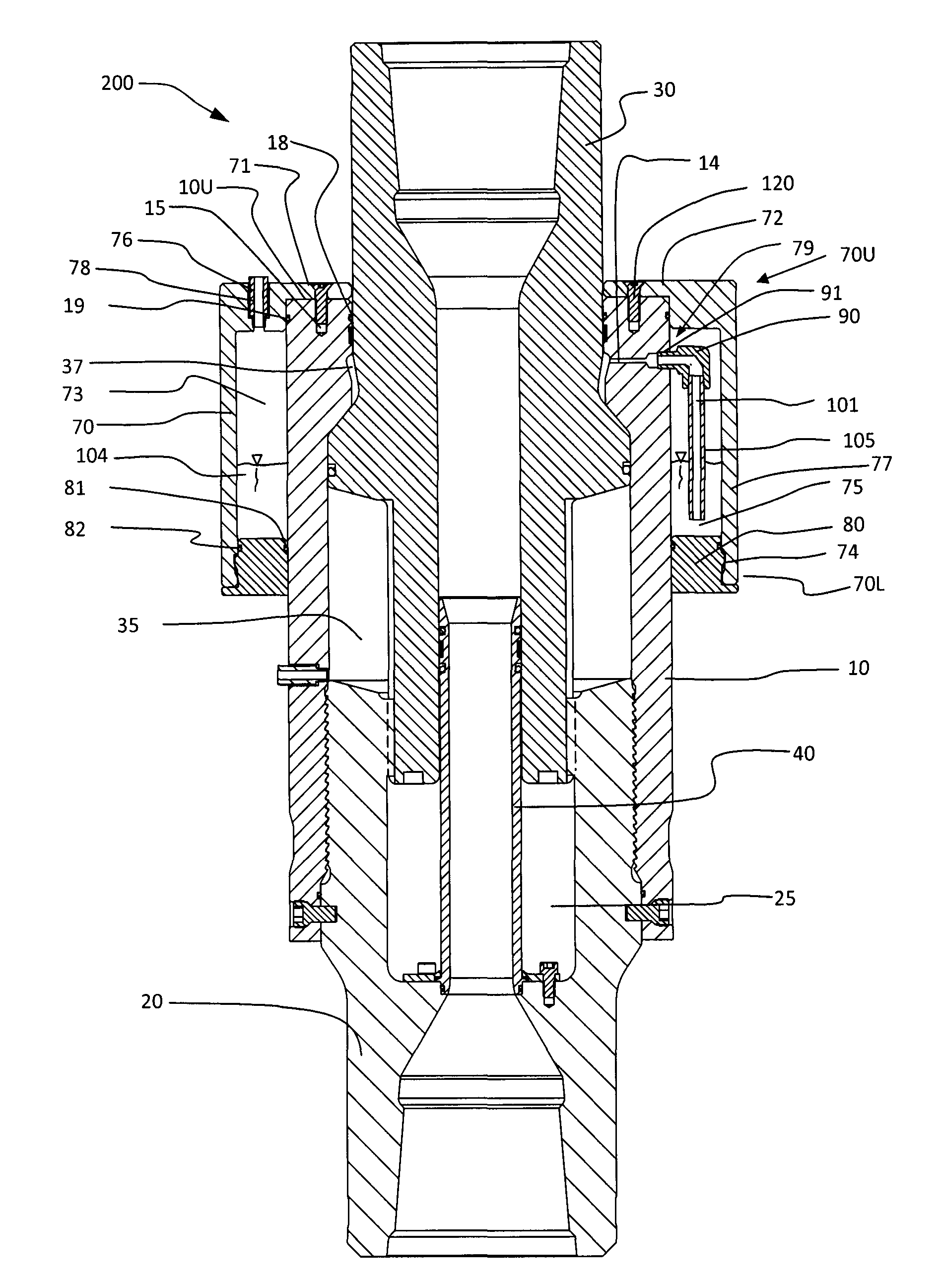
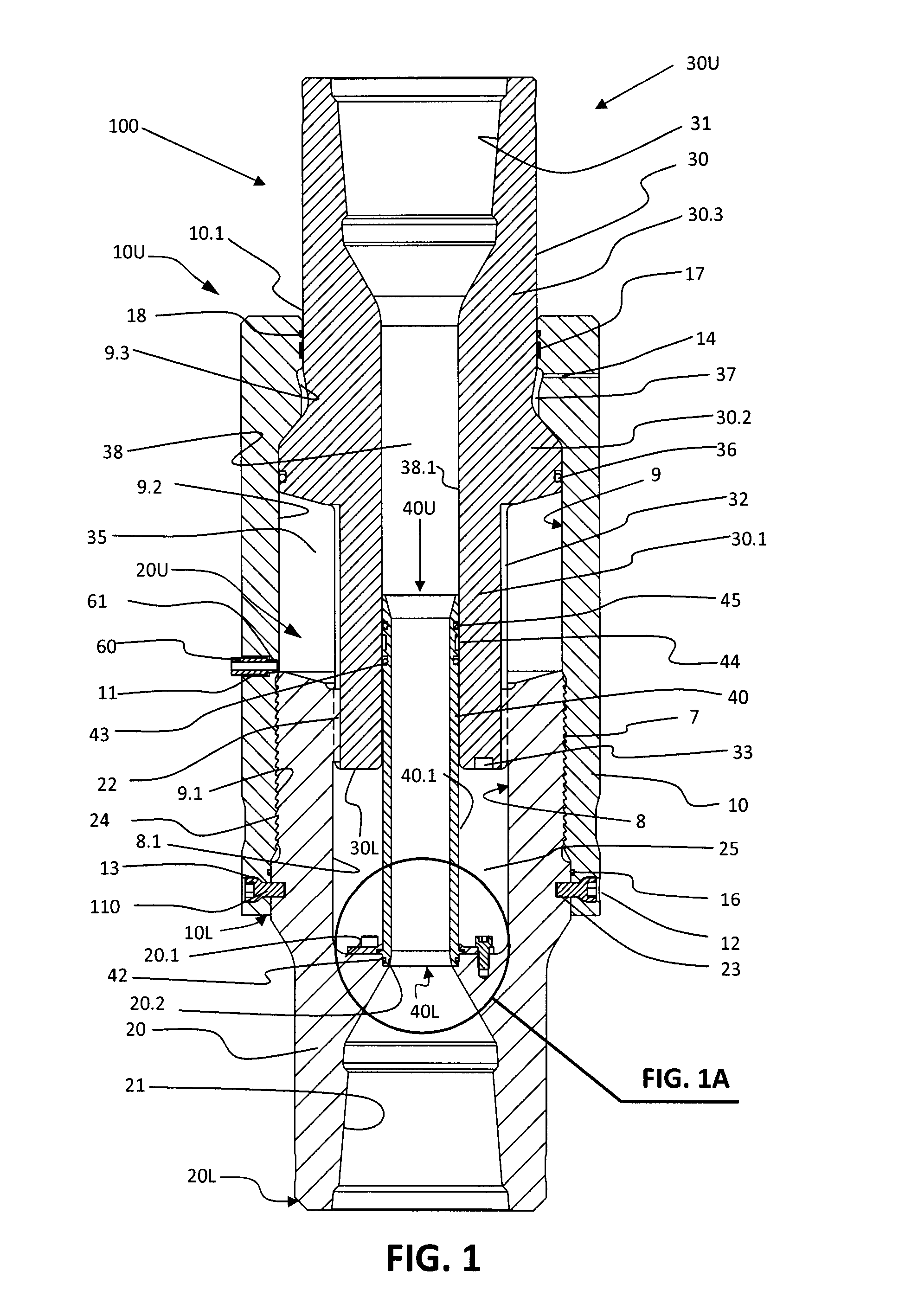
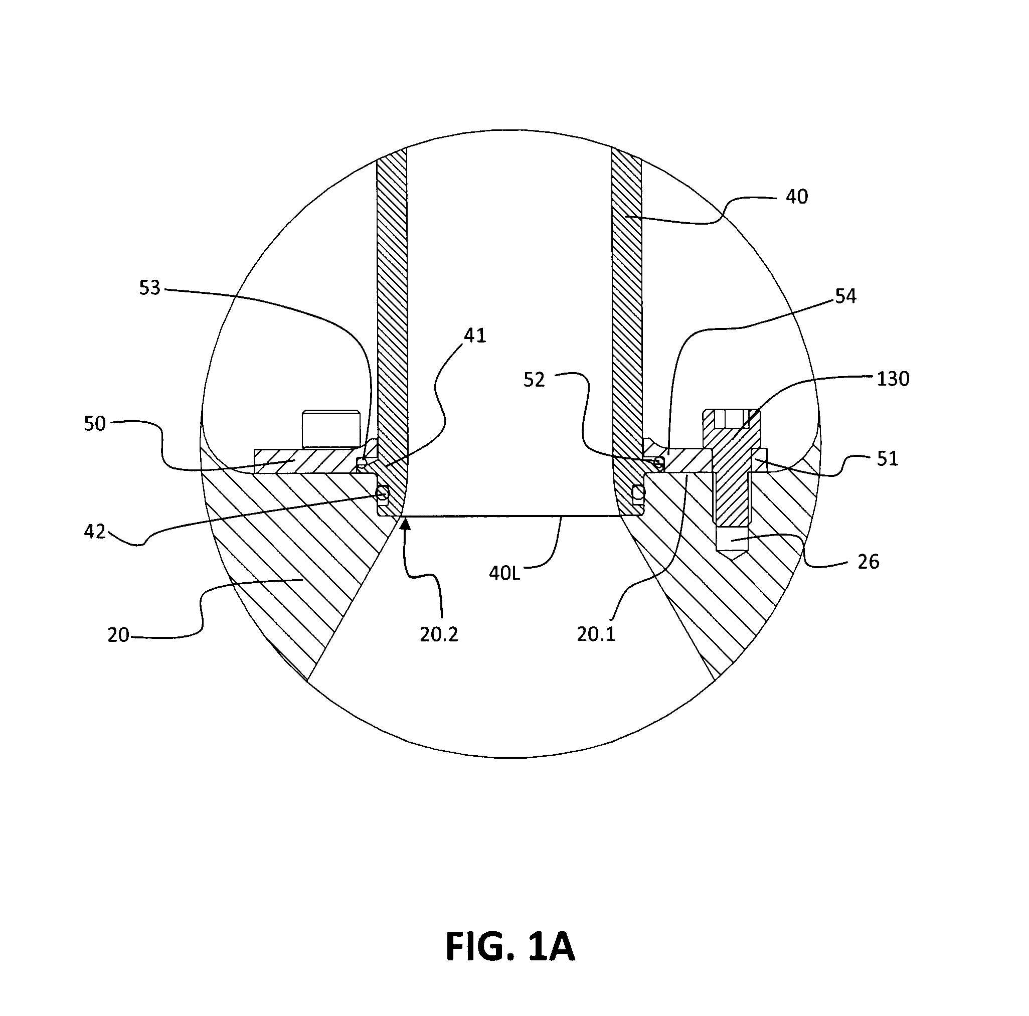
[0037]FIG. 1 is a longitudinal cross-section through a first embodiment of a floating sub tool (“FST”) 100 in accordance with the present disclosure, and shown in an axially extended position. FIG. 2 is similar to FIG. 1, but shows FST 100 in an axially contracted (or retracted) position.

[0038]In the illustrated embodiment, FST 100 comprises a generally cylindrical housing 10, a generally cylindrical lower member 20, a generally cylindrical upper member 30, and a cylindrical stinger 40 connected to lower member 20 as will be described herein. (In the oil and gas industry, the term “stinger” is commonly used with reference to a cylindrical or tubular member associated with a downhole tool or component, but having a relatively small diameter compared to the associated tool or component.) Housing 10, lower member 20, upper member 30, and stinger 40 are each generally axi-symmetric.

[0039]Housing 10 has an upper end 10U, a lower end 10L, and a longitudin...


PUM


Abstract

An axially-floating sub tool for axial load compensation in conjunction with a top drive comprises cylindrical upper and lower members, with the upper member being coaxially disposed within a cylindrical housing. The upper member has an upper section slidably disposed within an opening in the upper end of the housing, plus a middle section that slidably and sealingly engages the housing bore. The lower-member bore has a splined upper interval, and a coaxial stinger extending upward from an annular shoulder medially located in the lower-member bore. The lower member is connected to the lower end of the housing with the stinger slidingly and sealingly disposed within the upper-member bore, and with the lower-member splines slidingly engaging the upper-member splines, thus defining upper, middle, and lower annular chambers, with the middle and lower chambers in fluid communication, and with a regulator / check valve regulating pressure in the middle and lower chambers.

Description

FIELD OF THE DISCLOSURE[0001]The present disclosure relates in general to drill string components used to transmit rotary power and carry axial loads in top-drive-equipped drill rigs, and in particular to drill string components used in casing-running or casing-drilling operations for wells bored into subsurface formations.BACKGROUND[0002]Wells for production of hydrocarbon fluids such as oil and natural gas are typically drilled by connecting a drill bit to the lower end of a drill string made up of sections (or “joints”) of drill pipe connected end-to-end by means of threaded connections, and then rotating the drill bit into the ground until the bit penetrates a hydrocarbon-producing subsurface formation. After the well has been drilled, it is typically necessary to line the wellbore with tubular casing to prevent soil materials from sloughing into the wellbore and thus partially or completely collapsing the wellbore. Accordingly, after the drill string as been withdrawn from the ...

Claims


Application Information

Patent Timeline
Patent Type & Authority Patents(United States)
IPC IPC(8): E21B17/02
CPCE21B17/07E21B19/16
Inventor SLACK, MAURICE, WILLIAM
Owner NOETIC TECH INC
Why Eureka
Try Eureka