Charge clip

a charging clip and clip technology, applied in the direction of flexible/turnable line connectors, coupling device connections, transportation and packaging, etc., can solve the problems of charging electrical cords, unsightly manner, and limited counter space for charging devices in the kitchen

Active Publication Date: 2014-04-01
VOXX INTERNATIONAL
View PDF72 Cites 41 Cited by
  • Summary
  • Abstract
  • Description
  • Claims
  • Application Information

AI Technical Summary

Benefits of technology

[0011]It is a further object of the present invention to provide a charge clip for charging a PEI which includes an open cradle for supporting one or more PEIs and which cradle provides multi-directional accessibility to the PEIs supported by the cradle.
[0016]The power conversion plug further includes at least one outwardly extending rib that may be selectively engaged with a corresponding notch in the aperture of the main body. The power conversion plug is inserted into the wall outlet and the main body is rotated so that the cradle is vertically oriented to hold at least one PEI. The rib of the power conversion plug is then engaged with the notch in the main body making the main body and cradle thereon rotationally immovable with respect to the power conversion plug. In a preferred embodiment of the present invention, the charge clip includes a plurality of ribs and notches so that the power plug may be inserted into wall outlets of varying orientations while maintaining the vertical orientation of the cradle and PEI therein.

Problems solved by technology

The problem with this conventional method of charging a device is that the device being charged occupies the limited counter space in the kitchen and could be subject to damage due to spilled water or the like.
Furthermore, the charging electrical cord, usually about three feet in length, loosely lies on the countertop in an unsightly manner and may become entangled with objects residing on the countertop.
However, there are a number of disadvantages and shortcomings in the use and design of such a wall mounted charging station.
This wire connection may be lengthy, depending upon where the charging station 10 is positioned with respect to the wall outlet 14, and having such an unsupported loose wire may not be aesthetically pleasing in appearance.

Method used


Image

  • Charge clip
  • Charge clip
  • Charge clip

Examples


Embodiment Construction

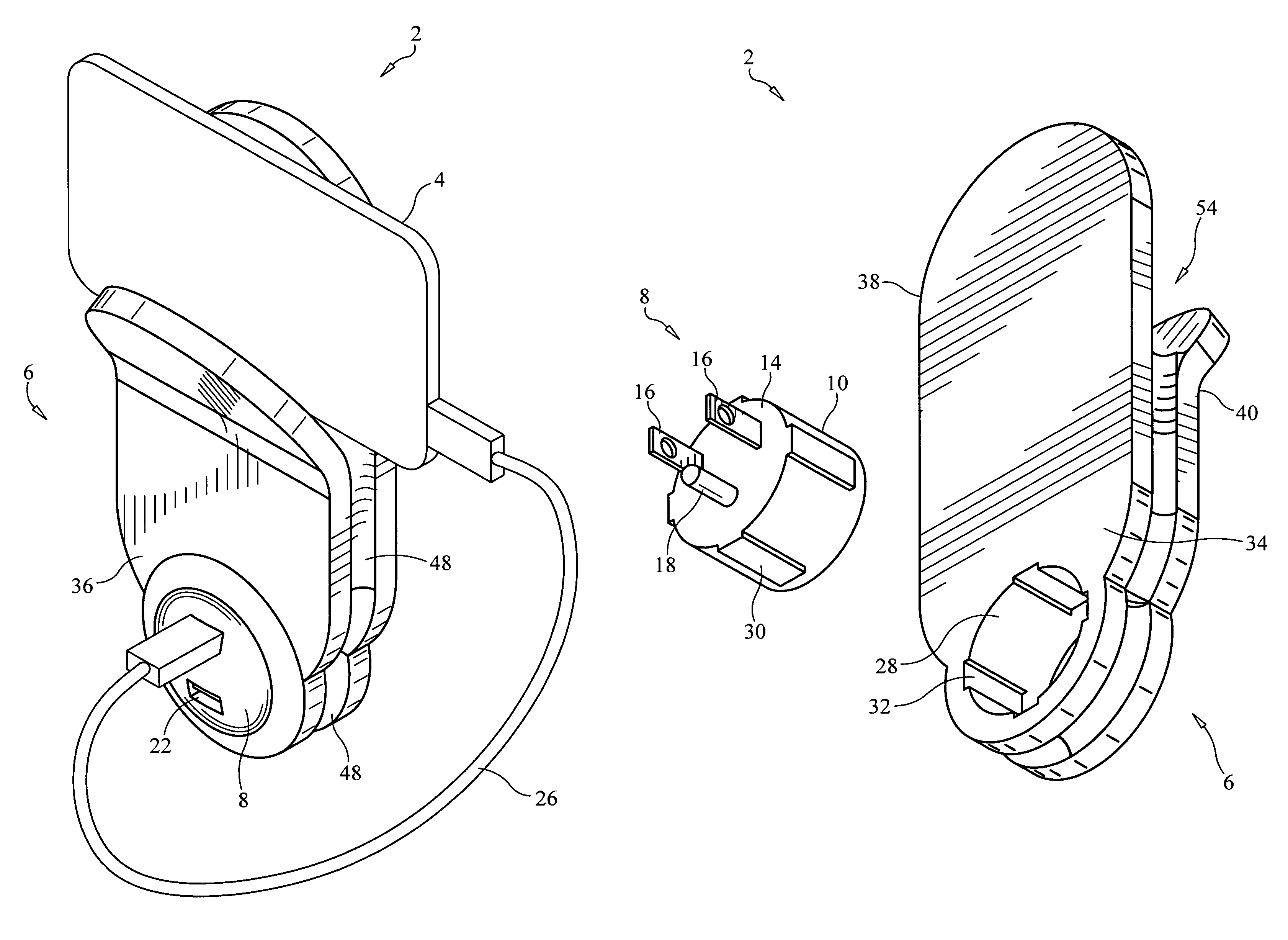
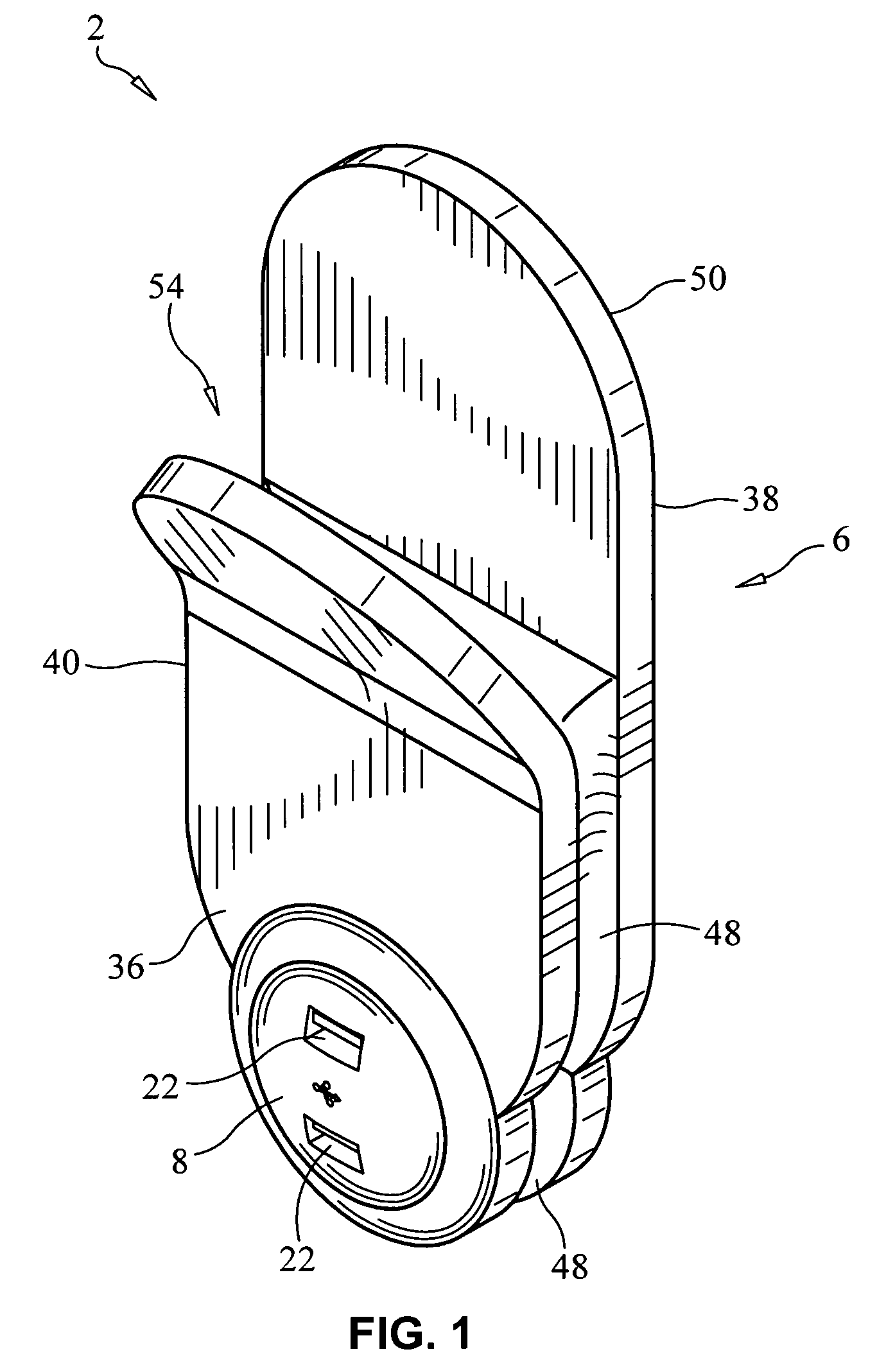
[0034]As can be seen from FIGS. 1-11, a charge clip 2 or station for charging a small appliance or electrical device, in particular but not limited to personal electronic instruments 4 such as cellular telephones, hand held gaming devices, digital cameras, PDAs, calculators and the like, and constructed in accordance with one form of the present invention, is preferably formed from two mateable portions, that is, a main body 6 and a power conversion plug 8.

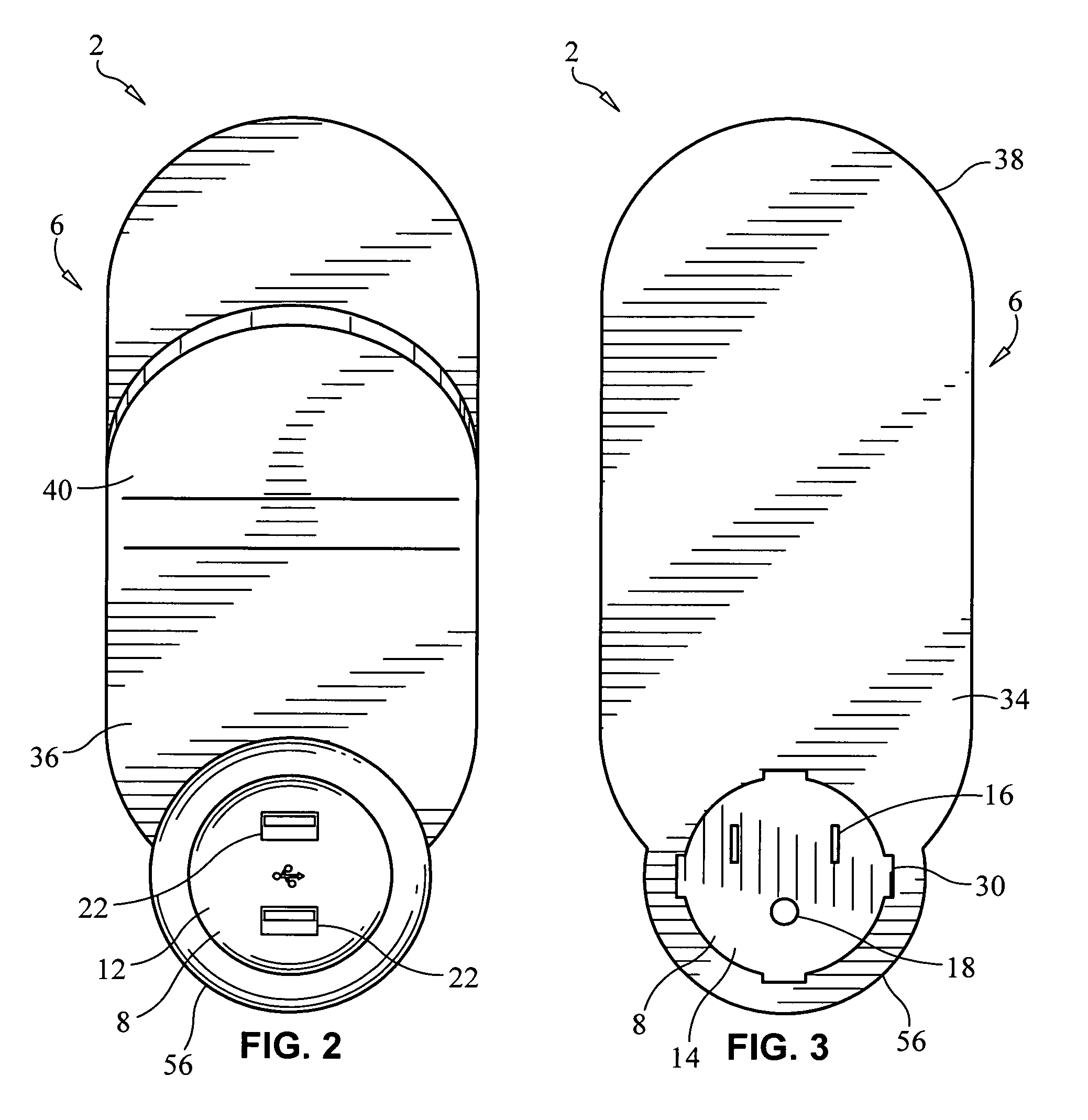
[0035]The power conversion plug 8 is preferably cylindrical in shape. The power conversion plug 8 includes a circumferential side wall 10, a front wall 12 which is preferably for aesthetic purposes convexly shaped, and a rear wall 14 which is opposite the front wall 12.

[0036]The rear wall 14 of the power conversion plug 8 includes hot and neutral AC power prongs 16 and an AC power ground prong 18 extending outwardly therefrom so that the power conversion plug 8 may be connected directly to a socket of an AC wall outlet 20.

[0037]At...


PUM


Abstract

A charge clip having a main body and plug received through an aperture therein includes a cradle for holding a personal electronic instrument (PEI) thereon. The plug is inserted into a wall outlet and the main body is selectively rotationally moveable with respect to the plug so that the main body is maintained in a vertical orientation regardless of the orientation of the wall outlet. The plug includes at least one rib that is selectively engageable with at least one notch formed in the aperture, preventing rotational movement of the main body with respect to the plug. The plug further includes an AC / DC conversion circuit that converts standard AC power from the wall outlet to DC power for charging the PEI. The charge clip further includes at least one USB port in electrical communication with the AC / DC conversion circuit that receives a USB plug in electrical communication with the PEI.

Description

CROSS-REFERENCE TO RELATED APPLICATIONS[0001]This application is related to U.S. Provisional Application Ser. No. 61 / 340,756, which was filed on Mar. 22, 2010, and is entitled “Charge Clip”, the disclosure of which is hereby incorporated by reference and on which priority is hereby claimed.BACKGROUND OF THE INVENTION[0002]1. Field of the Invention[0003]The present invention relates to devices for charging electrical equipment, in particular, personal electronic instruments such as cellular telephones, calculators, hand held gaming devices, digital cameras and the like.[0004]2. Description of the Prior Art[0005]Devices for charging portable electrical equipment, in particular, personal electronic instruments such as cellular telephones, hand held gaming devices, digital cameras, PDAs, calculators and the like usually plug into a wall outlet (120 volts AC) and include an AC to DC converter, which is coupled to a rather lengthy wire at one end whose opposite end is coupled to a connect...

Claims


Application Information

Patent Timeline
Patent Type & Authority Patents(United States)
IPC IPC(8): H02J7/00
CPCH02J7/0014H01R2103/00H02J2007/0062H02J7/0044H01R35/04H02J7/04H01R13/6675H01R31/065H02J7/007H01R2201/16H02J7/00
Inventor CASKEY, HENRY DALEBENEDETTI, DAVID ANTHONY
Owner VOXX INTERNATIONAL
Why Eureka
Try Eureka