Glass antenna for vehicle
a technology of glass antenna and vehicle, which is applied in the field of glass antenna, can solve the problems of limited space for mounting antennas, inability to achieve good looks and field of view, and complex antenna patterns, and achieves the effects of shortened development period, simplified antenna patterns, and easy tuning of antenna characteristics
- Summary
- Abstract
- Description
- Claims
- Application Information
AI Technical Summary
Benefits of technology
Problems solved by technology
Method used
Image
Examples
first embodiment
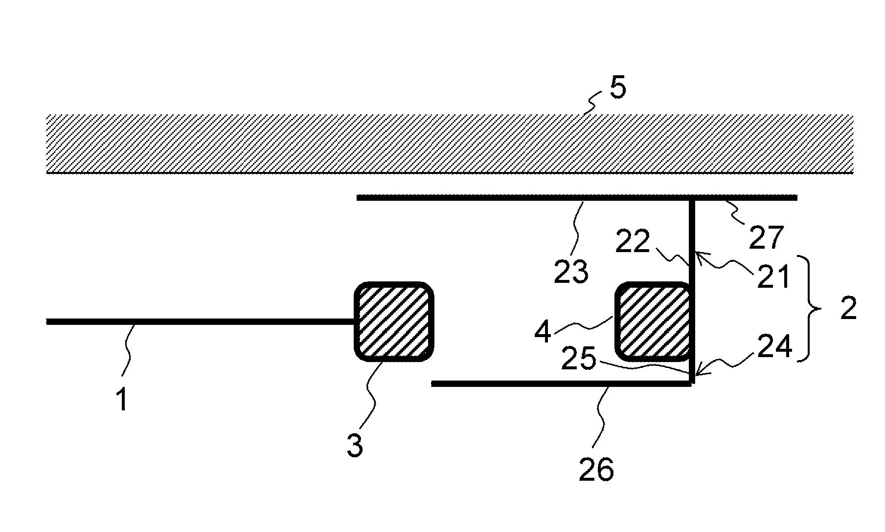
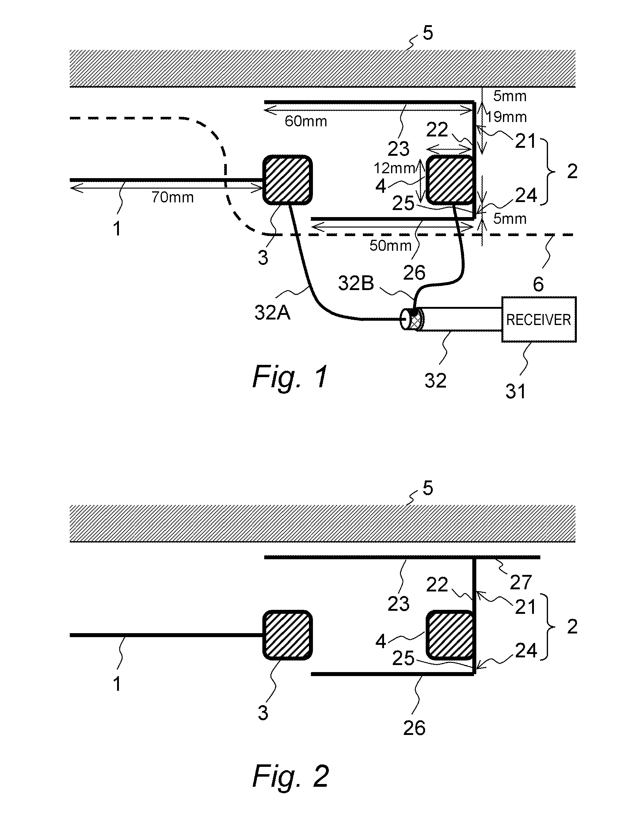
[0038]FIG. 1 illustrates a configuration of a glass antenna according to a first embodiment of this invention.
[0039]The glass antenna according to the embodiments of this invention comprises a core-side element 1 and a ground-side element 2. The core-side element 1 is connected to a feed terminal 3 and the ground-side element 2 is connected to a feed terminal 4. The feed terminals 3 and 4 are connected to a receiver 31 (for example, a television set) via feeder cables 32A and 32B.
[0040]The ground-side element 2 comprises a first element 21 connected to an upper part of the feed terminal 4 and a second element 24 connected to a lower part thereof.
[0041]The first element 21 extends upward from the right end of the feed terminal 4 to form a vertical part 22. It should be noted that the vertical part 22 may extend from the left end or the middle of the feed terminal 4 as in the tenth and eleventh embodiments, which will be described later.
[0042]The end of the vertical part 22 bends in t...
second embodiment
[0062]FIG. 2 illustrates a configuration of a glass antenna according to a second embodiment of this invention.
[0063]The glass antenna according to the second embodiment is an antenna with a horizontal part (an auxiliary element) 27 added to the ground-side element 2 of the above-described glass antenna according to the first embodiment.
[0064]The glass antenna according to the second embodiment comprises a core-side element 1 on the feed side and a ground-side element 2. The core-side element 1 is connected to a feed terminal 3. The ground-side element 2 comprises a first element 21 connected to an upper part of a feed terminal 4 and a second element 24 connected to a lower part thereof. A horizontal part 26 of the second element 24 extends to the proximity of the feed terminal 3.
[0065]The first element 21 extends upward from the feed terminal 4 to form a vertical part 22. Then, the end of the vertical part 22 bends in the direction of the feed terminal 3 (leftward) and extends to t...
third embodiment
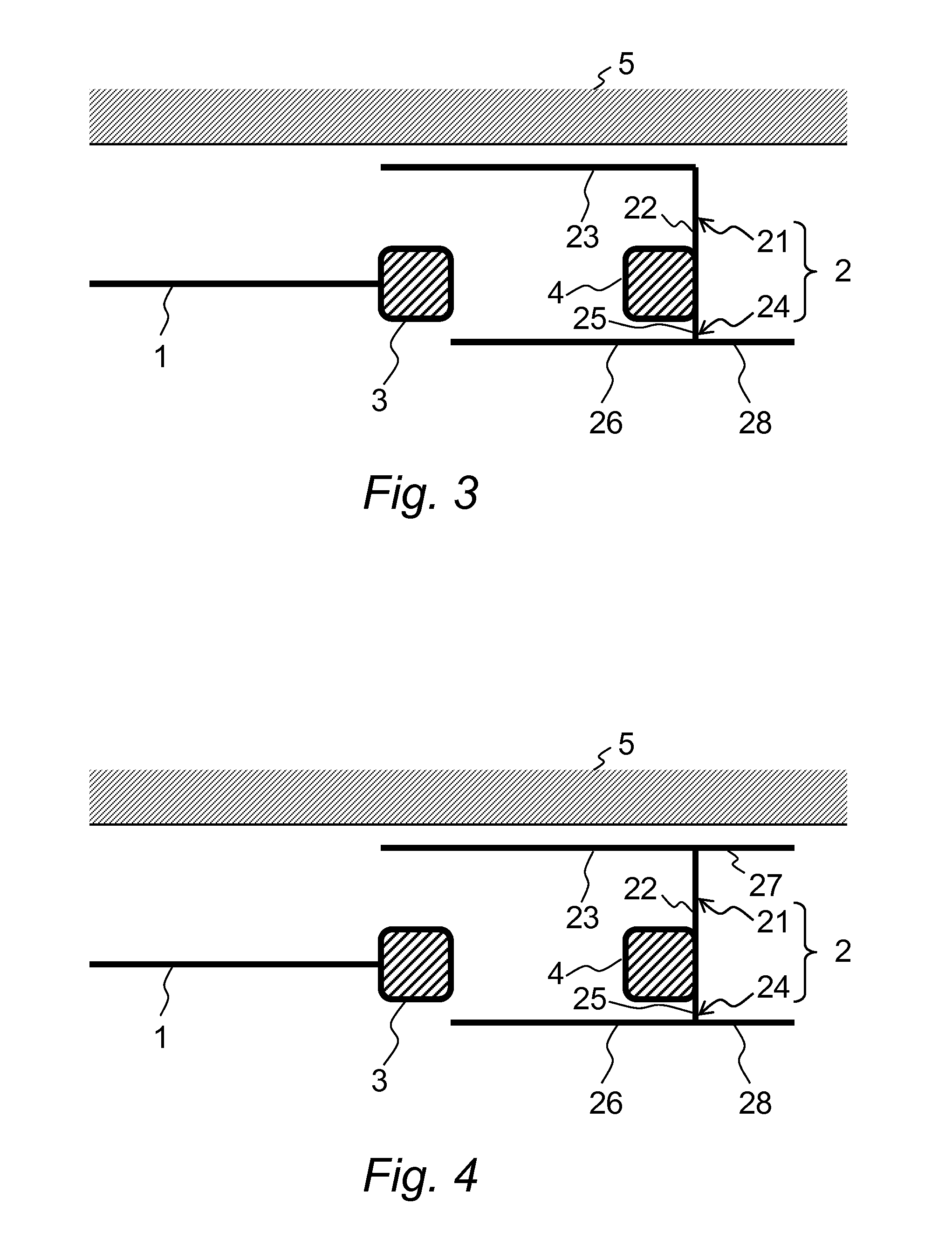
[0069]FIG. 3 illustrates a configuration of a glass antenna according to a third embodiment of this invention.
[0070]The glass antenna according to the third embodiment is an antenna with a horizontal part (an auxiliary element) 28 added to the ground-side element 2 of the above-described glass antenna according to the first embodiment.
[0071]The glass antenna according to the third embodiment comprises a core-side element 1 on the feed side and a ground-side element 2. The core-side element 1 is connected to a feed terminal 3. The ground-side element 2 comprises a first element 21 connected to an upper part of a feed terminal 4 and a second element 24 connected to a lower part thereof. The entirety of a horizontal part 23 of the first element 21 is configured to capacitively couple with the body flange.
[0072]The second element 24 extends downward from the feed terminal 4 to form a vertical part 25. Then, the end of the vertical part 25 bends in the direction of the feed terminal 3 (l...
PUM
 Abstract
Description
Claims
Application Information
 - R&D
- Intellectual Property
- Life Sciences
- Materials
- Tech Scout
- Unparalleled Data Quality
- Higher Quality Content
- 60% Fewer Hallucinations
Browse by: Latest US Patents, China's latest patents, Technical Efficacy Thesaurus, Application Domain, Technology Topic, Popular Technical Reports.
© 2025 PatSnap. All rights reserved.Legal|Privacy policy|Modern Slavery Act Transparency Statement|Sitemap|About US| Contact US: help@patsnap.com


