Glass antenna for vehicle

a technology of glass antenna and vehicle, which is applied in the field of glass antenna, can solve the problems of limited space for mounting antennas, inability to achieve good looks and field of view, and complex antenna patterns, and achieves the effects of shortened development period, simplified antenna patterns, and easy tuning of antenna characteristics

Inactive Publication Date: 2011-02-17
CENT GLASS CO LTD
View PDF15 Cites 13 Cited by
  • Summary
  • Abstract
  • Description
  • Claims
  • Application Information

AI Technical Summary

Benefits of technology

[0014]The antenna of this invention achieves a simpler antenna pattern and ensures required antenna sensitivity by an arrangement in which one element line of a ground-side element is arranged close to the body flange while another element line of the ground-side element is arranged on the opposite side. Accordingly, a compact and high-performance antenna can be provided that will not be a disturbance to the driver's field of view even if the antenna is mounted on the front window glass.
[0015]Furthermore, one element line of the ground-side element is arranged close to the body flange and the other element line of the ground-side element is arranged on the opposite side. so easy tuning of the antenna characteristics is achieved and the development period is shortened.
[0016]Furthermore, at least a part of antenna elements, conductive parts, and feed terminals is arranged on ceramic paste, so the antenna is hardly seen from the outside of the vehicle, providing good looks. Besides, at least a part of the antenna elements, the conductive parts, and the feed terminals are covered with the vehicle interior material made of resin, providing good looks from the inside of the vehicle likewise.

Problems solved by technology

To mount such an antenna on a rear window glass, the space for mounting the antenna is limited because defogging heating lines are arranged over most of the area of the rear window glass.
Accordingly, the antenna pattern has been more complex, so good looks and the field of view can not be achieved.
In addition, the increase in the number of element lines has caused a problem of increase in time and costs for tuning development.

Method used


Image

  • Glass antenna for vehicle
  • Glass antenna for vehicle
  • Glass antenna for vehicle

Examples


first embodiment

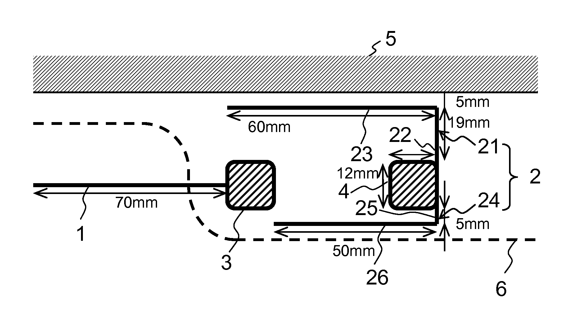
[0038]FIG. 1 illustrates a configuration of a glass antenna according to a first embodiment of this invention.

[0039]The glass antenna according to the embodiments of this invention comprises a core-side element 1 and a ground-side element 2. The core-side element 1 is connected to a feed terminal 3 and the ground-side element 2 is connected to a feed terminal 4. The feed terminals 3 and 4 are connected to a receiver (for example, a television set) via feeder cables.

[0040]The ground-side element 2 comprises a first element 21 connected to an upper part of the feed terminal 4 and a second element 24 connected to a lower part thereof.

[0041]The first element 21 extends upward from the right end of the feed terminal 4 to form a vertical part 22. It should be noted that the vertical part 22 may extend from the left end or the middle of the feed terminal 4 as in the tenth and eleventh embodiments, which will be described later.

[0042]The end of the vertical part 22 bends in the direction of...

second embodiment

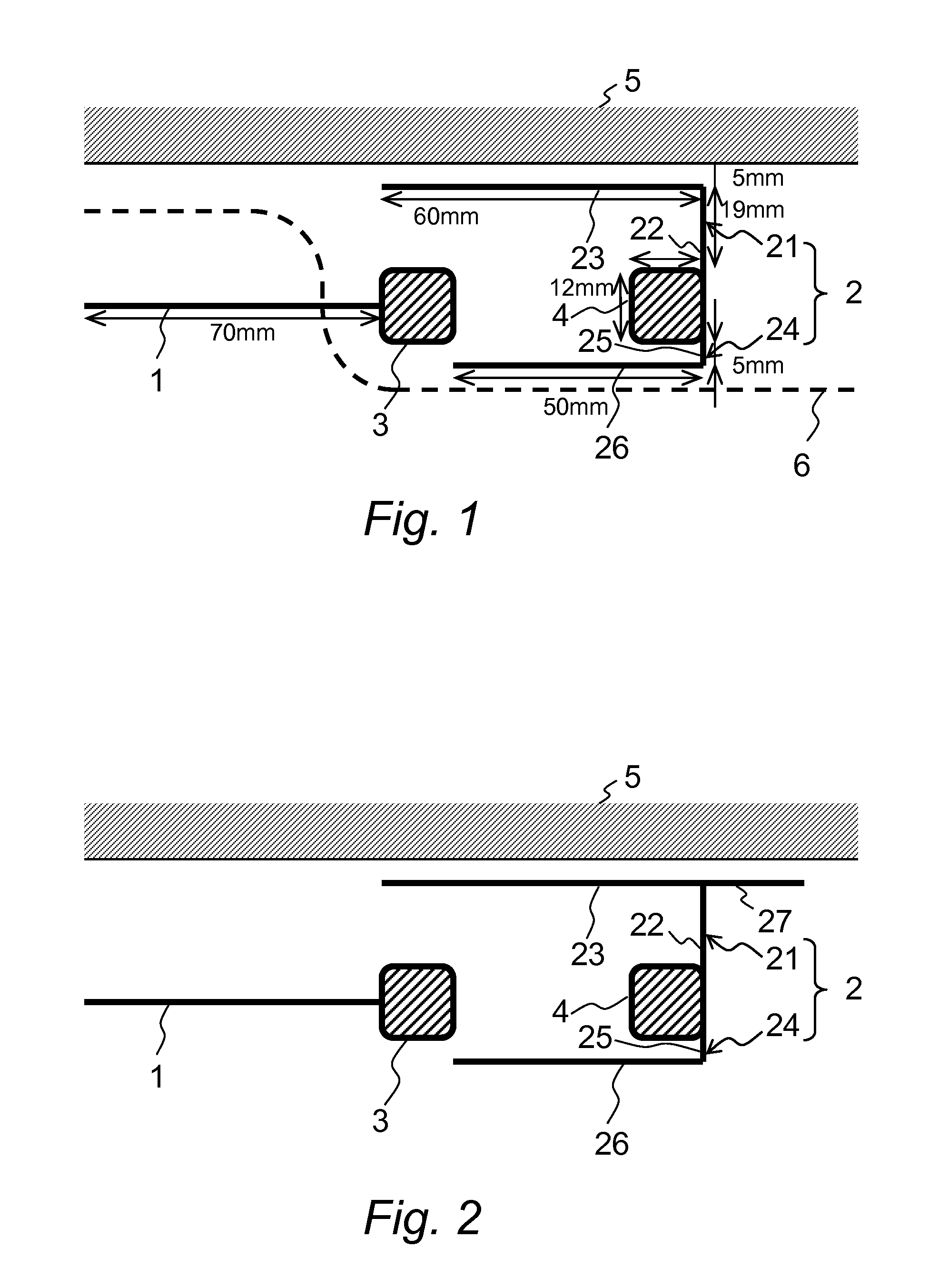
[0062]FIG. 2 illustrates a configuration of a glass antenna according to a second embodiment of this invention.

[0063]The glass antenna according to the second embodiment is an antenna with a horizontal part (an auxiliary element) 27 added to the ground-side element 2 of the above-described glass antenna according to the first embodiment.

[0064]The glass antenna according to the second embodiment comprises a core-side element 1 on the feed side and a ground-side element 2. The core-side element 1 is connected to a feed terminal 3. The ground-side element 2 comprises a first element 21 connected to an upper part of a feed terminal 4 and a second element 24 connected to a lower part thereof. A horizontal part 26 of the second element 24 extends to the proximity of the feed terminal 3.

[0065]The first element 21 extends upward from the feed terminal 4 to form a vertical part 22. Then, the end of the vertical part 22 bends in the direction of the feed terminal 3 (leftward) and extends to t...

third embodiment

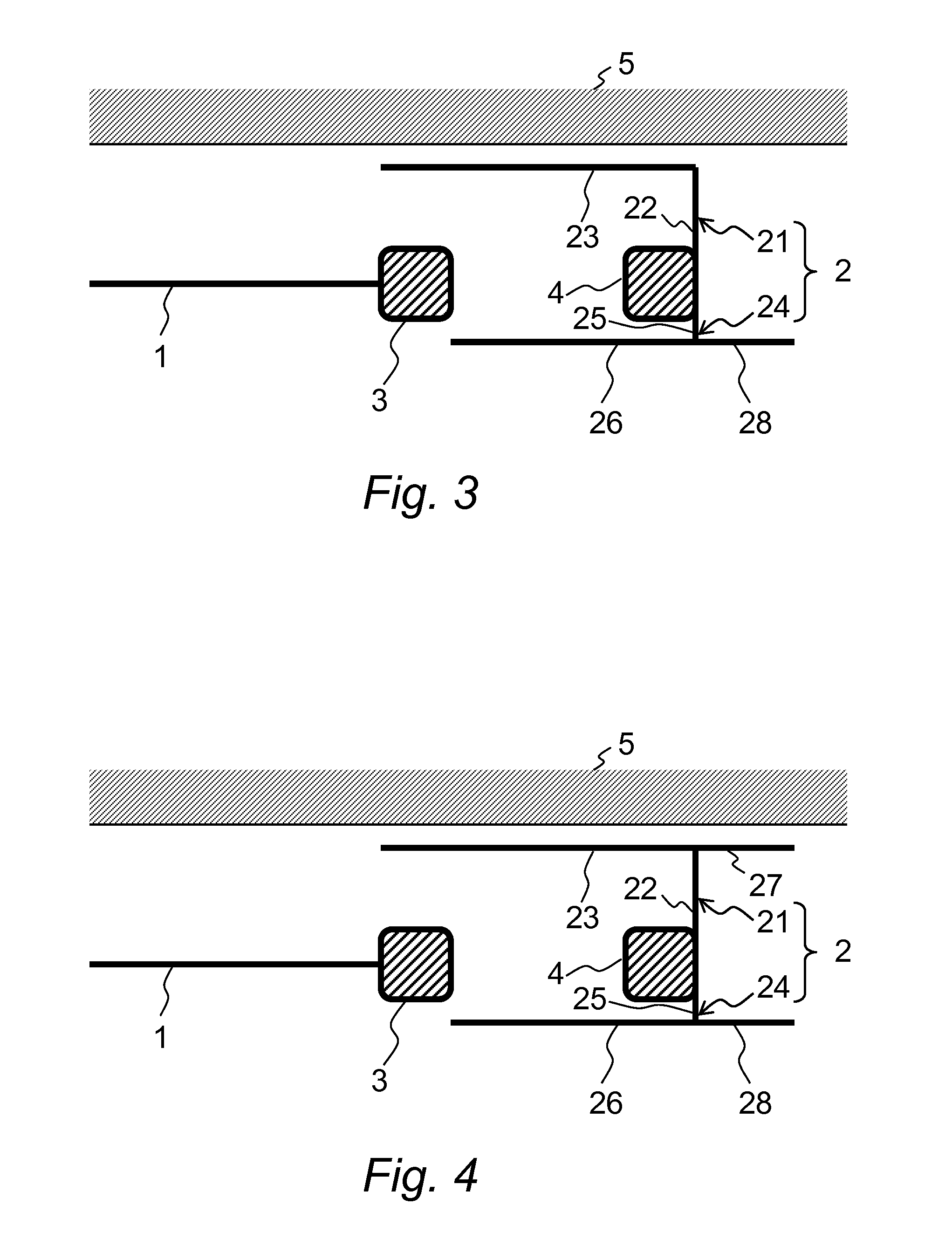
[0069]FIG. 3 illustrates a configuration of a glass antenna according to a third embodiment of this invention.

[0070]The glass antenna according to the third embodiment is an antenna with a horizontal part (an auxiliary element) 28 added to the ground-side element 2 of the above-described glass antenna according to the first embodiment.

[0071]The glass antenna according to the third embodiment comprises a core-side element 1 on the feed side and a ground-side element 2. The core-side element 1 is connected to a feed terminal 3. The ground-side element 2 comprises a first element 21 connected to an upper part of a feed terminal 4 and a second element 24 connected to a lower part thereof. The entirety of a horizontal part 23 of the first element 21 is configured to capacitively couple with the body flange.

[0072]The second element 24 extends downward from the feed terminal 4 to form a vertical part 25. Then, the end of the vertical part 25 bends in the direction of the feed terminal 3 (l...


PUM


Abstract

To provide a sensitive antenna with simple pattern, there is provided an antenna comprising: a core-side element connected to a core-side feed point; and a ground-side element connected to a ground-side feed point, wherein: the core-side element extends from the core-side feed point in a predetermined direction; the ground-side element includes: a first element which is connected to the ground-side feed point and extends in parallel to the core-side element; and a second element which is connected to the ground-side feed point and extends in parallel to the first element; and the first element is located close to a body flange to capacitively couple with the body flange.

Description

BACKGROUND OF THE INVENTION[0001]This invention relates to an antenna, and, in particular, relates to a glass antenna which is to be mounted on a vehicle window glass and is suitable for receiving digital terrestrial TV broadcast signals and UHF analog TV broadcast signals.[0002]For vehicle glass antennas, antennas to be mounted in the spaces upper or lower than heating conductive lines of defogger on rear window glasses have been developed and widely known so far (for example, refer to JP 2008-124822 A, JP 2005-354139 A, JP 2008-135944 A, and JP 2007-150966 A). To mount such an antenna on a rear window glass, the space for mounting the antenna is limited because defogging heating lines are arranged over most of the area of the rear window glass.[0003]Besides, to improve the antenna sensitivity of a rear window glass antenna, the number of elements is increased or vertical elements are added within the defogger area. Accordingly, the antenna pattern has been more complex, so good lo...

Claims


Application Information

Patent Timeline
Patent Type & Authority Applications(United States)
IPC IPC(8): H01Q1/32
CPCH01Q1/1271H01Q9/42H01Q9/30H01Q9/16
Inventor MUKAI, HIROSHIKAIHATSU, MASANORI
Owner CENT GLASS CO LTD
Why Eureka
Try Eureka