Surface mounting apparatus

a technology for mounting apparatuses and surface mounts, which is applied in the direction of metal working apparatuses, metal-working machine components, manufacturing tools, etc., can solve the problems of inaccurate correction, inability to determine the change in the interior of the camera, and the board recognizing camera itself undergoes temporal change, etc., to achieve easy and accurate correction for temporal change

Active Publication Date: 2014-04-22
JUKI CORP
View PDF9 Cites 1 Cited by
  • Summary
  • Abstract
  • Description
  • Claims
  • Application Information

AI Technical Summary

Benefits of technology

[0011]The invention provides a surface mounting apparatus capable of easily and accurately correcting for temporal change in the optical system within the board recognizing camera 16 configured to move integrally with the mounting head 10.

Problems solved by technology

However, there is a problem that the board recognizing camera itself undergoes temporal change.
Accordingly, the method of the related art has the problem that a correction cannot be accurate because the result of imaging is inevitably influenced by temporal change in the interior of the camera including the optical system.
Thus, the change in the interior of the camera cannot be determined by this technique.
Consequently, the technique disclosed in the Japanese Patent No. 3129134 has a similar problem.

Method used


Image

  • Surface mounting apparatus
  • Surface mounting apparatus
  • Surface mounting apparatus

Examples


Embodiment Construction

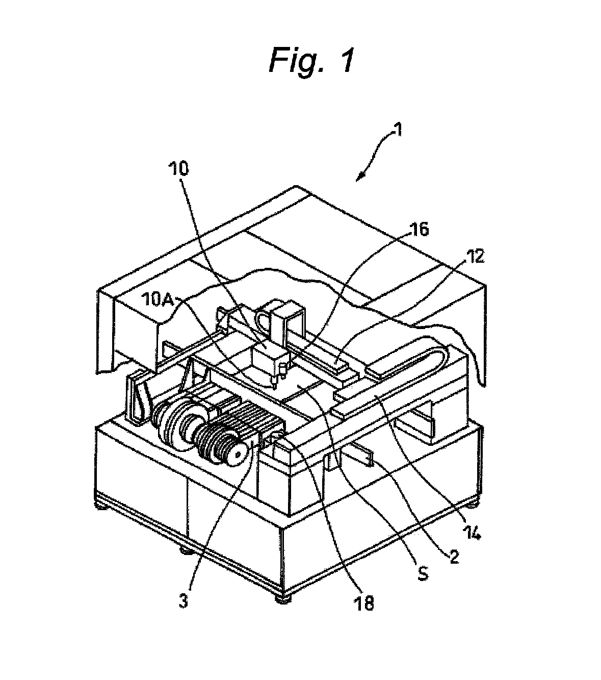
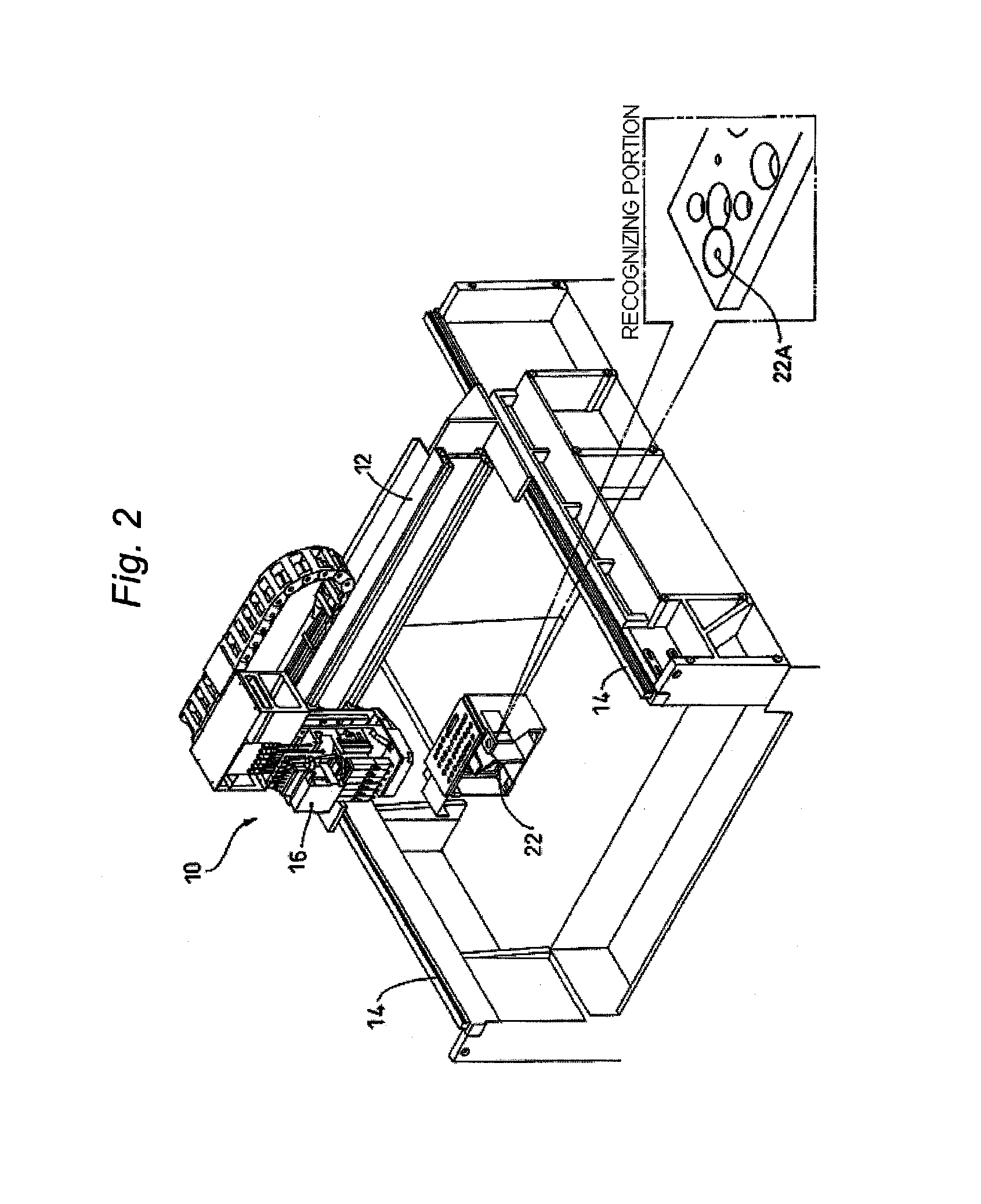
[0023]Hereinafter, an embodiment of the invention is described in detail with reference to FIGS. 1 to 7.

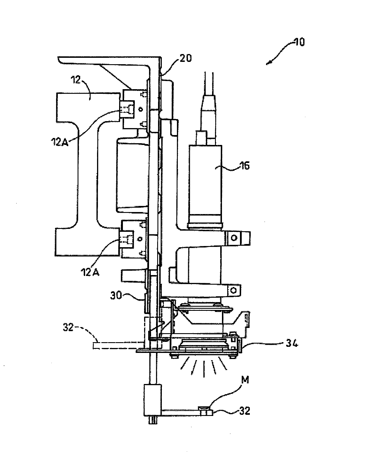
[0024]FIG. 4 is a left side view of a mounting head 10 shown in FIG. 3. Incidentally, a fundamental configuration of a surface mounting apparatus according to the present embodiment is the same as the configuration illustrated in FIGS. 1 to 3. Thus, each component of the present embodiment which is unchanged is designated with the same reference numeral. Consequently, the detailed description of the fundamental configuration is omitted.

[0025]A base 20 to which the mounting head 10 is attached is supported by a guide 12A of a X-axis direction drive mechanism 12 so as to be movable in the X-direction which is perpendicular to the plane of a paper. A board recognizing camera 16 is also fixed to the base 20, so that the board recognizing camera 16 can move integrally with the mounting head 10.

[0026]According to the present embodiment, a bar-like correction jig 32 extending horizontall...


PUM

PropertyMeasurementUnit
heightaaaaaaaaaa
temperatureaaaaaaaaaa
timeaaaaaaaaaa

Abstract

A surface mounting apparatus includes a mounting head which is movable in X and Y directions and which mounts an electronic component on a positioned board, and a board recognizing camera is fixed to a base and which moves integrally with the mounting head. A correction jig includes a correction mark which is imaged by the board recognizing camera, and an imaging result is used to correct temporal change in an interior portion of the camera including an optical system, and is fixed to the base.

Description

FIELD OF THE INVENTION[0001]The present invention relates to a surface mounting apparatus suitable for improving a correcting accuracy of a board recognizing camera which images a board mark to correct the fixing position where an electronic component is mounted on a board.DESCRIPTION OF RELATED ART[0002]Usually, as illustrated in FIG. 1, an electronic component mounting apparatus 1 comprises a component supply portion 3 retaining a component to be mounted, a mounting head 10 including a sucking nozzle 10A for sucking the component, and an X-axis direction moving mechanism 12 and a Y-axis direction moving mechanism 14, which move the mounting head 10 in an X-direction and a Y-direction, respectively. A board S is moved on a board transport path 2 extending along one direction to position the board S. Subsequently, the mounting head 10 is moved to a predetermined position on the positioned board S. Then, the electronic component held by the mounting head 10 is mounted at the predeter...

Claims


Application Information

Patent Timeline
Patent Type & Authority Patents(United States)
IPC IPC(8): H05K13/08
CPCH05K13/0413H05K13/08H05K13/0812Y10T29/53174Y10T29/53091Y10T29/53178Y10T29/49131
Inventor KAGAYA, HIROYUKI
Owner JUKI CORP
Why Eureka
Try Eureka