
Displaying method and portable electronic device using the same

a portable electronic device and display method technology, applied in the field of display methods, can solve the problems of limited hardware efficiency of the portable electronic device b>1/b>, deterioration of operation comfort, and un-displayability of the lower portion b>122/b>, so as to reduce the effect of visual segmentation or discomfort in operation, and reduce the difficulty of displaying

Active Publication Date: 2014-05-06
PEGATRON
View PDF15 Cites 0 Cited by
  • Summary
  • Abstract
  • Description
  • Claims
  • Application Information

AI Technical Summary

Benefits of technology

This method eliminates the frame sticking or mosaic phenomenon, providing a comfortable user experience by allowing the frame to rearrange without direct visual interference, while maintaining portability and cost-effectiveness without additional hardware.

Problems solved by technology

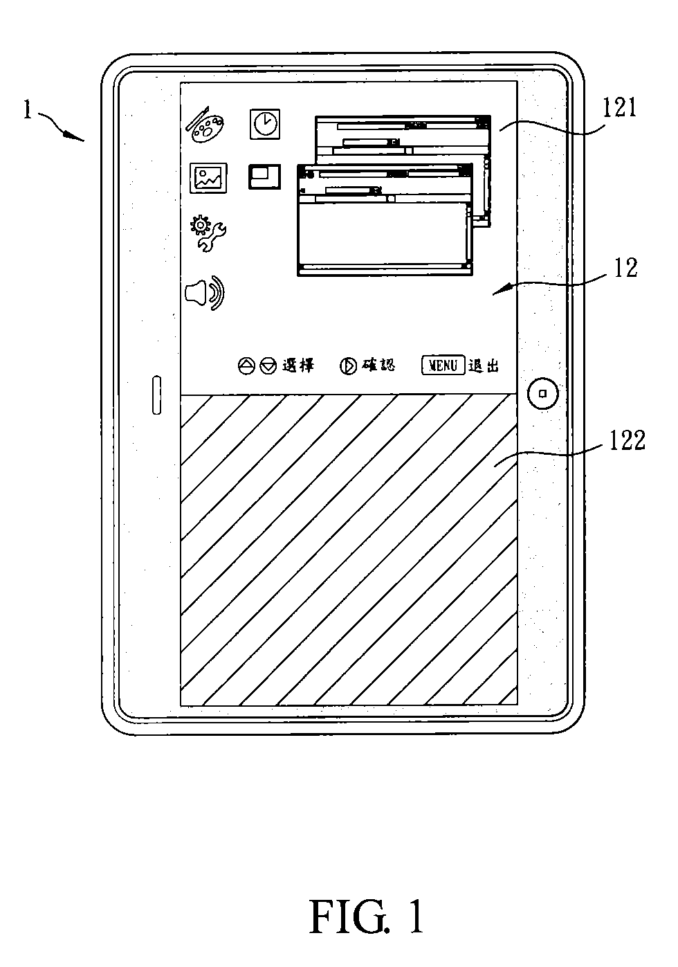
However, since the hardware efficiency of the portable electronic device 1 is limited, the frame 12 may fail to be re-arranged to be adjusted to a vertical one, and therefore the lower portion 122 may remain un-displayed.
Accordingly, visual segmentation may be felt by the user, thus deteriorating comfort in operation.

Method used


Image

  • Displaying method and portable electronic device using the same
  • Displaying method and portable electronic device using the same
  • Displaying method and portable electronic device using the same

Examples


first embodiment

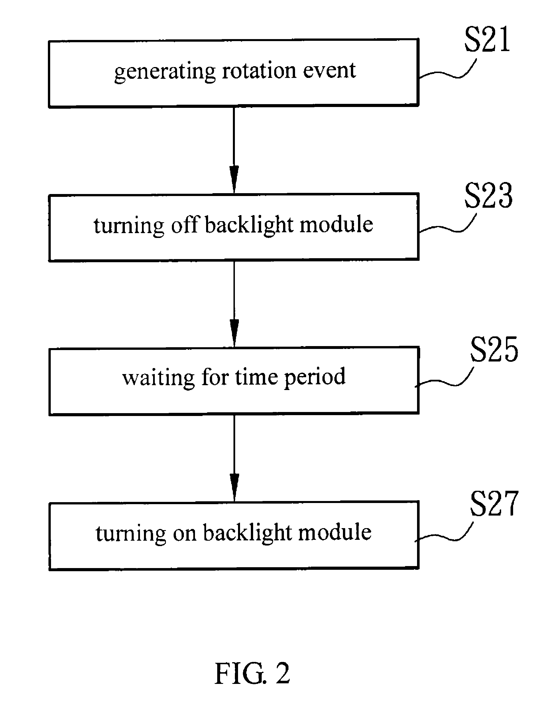
[0038]FIG. 2 is a flow chart showing a displaying method according to the invention. In FIG. 2, the displaying method includes the following steps: generating a rotation event (step S21); turning off a backlight module (step S23); waiting for a time period (step S25); turning on the backlight module (step S27).

[0039]Since the displaying method aforementioned is used in a portable electronic device, it may be described with the portable electronic device and the elements thereof hereinbelow.

[0040]FIG. 3A is a schematic diagram showing a portable electronic device where the displaying method according to the first embodiment of the invention is used, and FIG. 3B is a system block diagram showing the portable electronic device in FIG. 3A. In FIG. 3A, the portable electronic device 3 may include a rotation sensing unit 31, a processing unit 32, a display panel 33, a timing unit 34, and a flash memory FM. The processing unit 32 includes an embedded controller EC. The display panel 33 has...

second embodiment

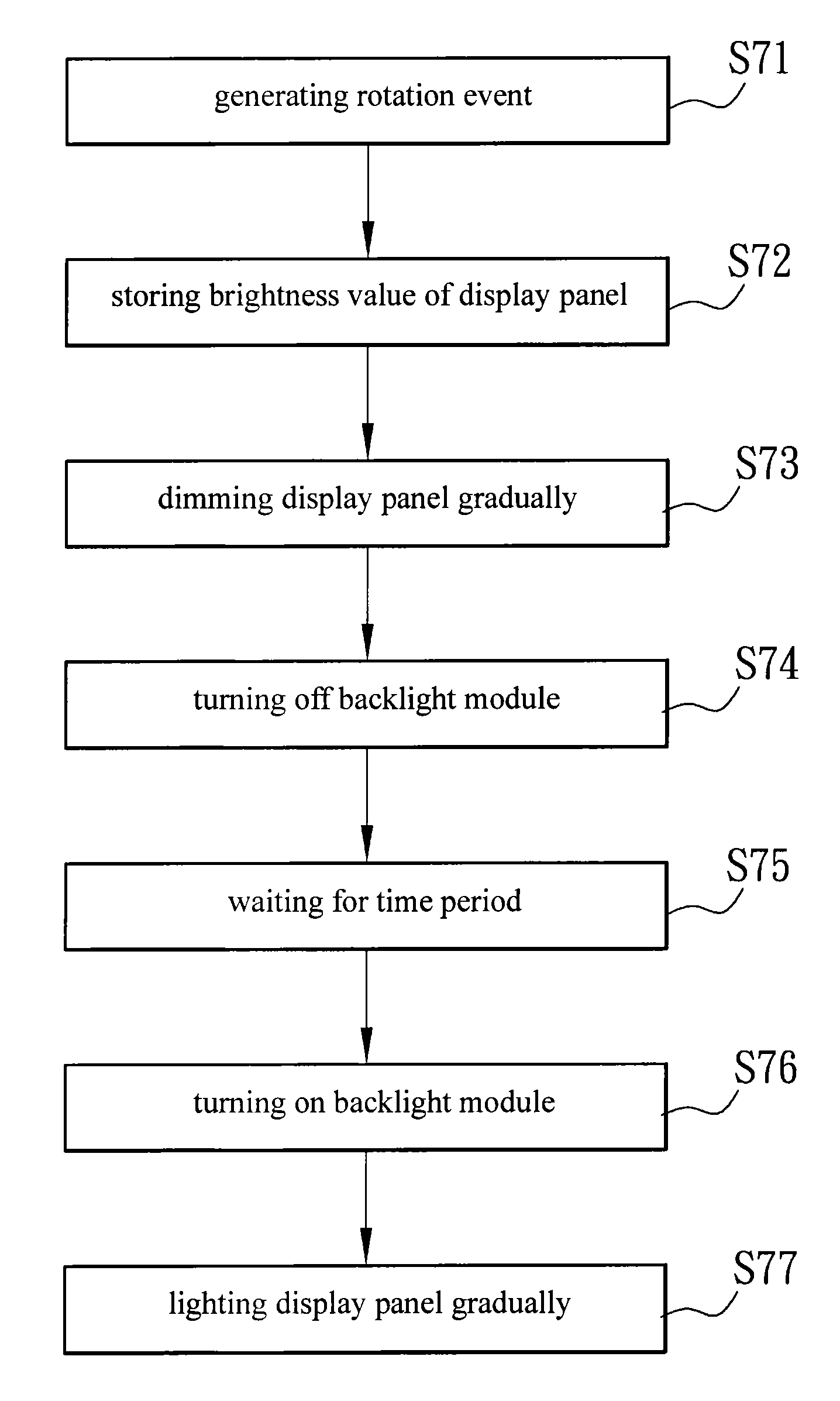
[0053]FIG. 8 is a schematic diagram showing a displayed frame when a display panel of a portable electronic device where the displaying method according to the invention is used is dimmed gradually. Please refer to FIG. 8 together. In step S73, after the brightness value is stored by the portable electronic device 8 via the aforementioned brightness application and before the backlight module is turned off, the processing unit can dim the display panel 83 gradually according to the signal or instruction from the resident program. Preferably, the processing unit adopts the same brightness application to adjust the brightness value directly via the interface provided by the operating system. However, the invention is not limited thereto. In the embodiment, gradual dimming means dimming the display panel 83 as time goes on till the user fails to see the displayed frame. Certainly, the display panel 83 can be dimmed to the lowest brightness value. However, the invention is not limited t...


PUM


Abstract

A displaying method used in a portable electronic device is provided. The portable electronic device includes a display panel having a backlight module. The displaying method includes the following steps: turning off the backlight module when a rotation event occurs; waiting for a time period; turning on the backlight module.

Description

CROSS-REFERENCE TO RELATED APPLICATIONS[0001]This Non-provisional application claims priority under 35 U.S.C. §119(a) on Patent Application No(s). 099132106 filed in Taiwan, Republic of China on Sep. 21, 2010, the entire contents of which are hereby incorporated by reference.BACKGROUND OF THE INVENTION[0002]1. Field of the Invention[0003]This invention relates to a displaying method and, more particularly, to a displaying method used in a portable electronic device.[0004]2. Description of the Related Art[0005]At present, a portable electronic device plays an important role in people's daily life. A tablet computer, a smart phone, a personal digital assistant, or a portable navigation device facilitates people's life. A user can access Internet, send and receive e-mails, search data, watch TV programs, play games, see films, or browse photos via the portable electronic device anytime.[0006]Besides easy carry, the portable electronic device can be used horizontally or vertically accor...

Claims


Application Information

Patent Timeline
Patent Type & Authority Patents(United States)
IPC IPC(8): G09G3/36
CPCH05B37/0227H05B47/105
Inventor HUANG, HSIAO-MINGWANG, YU-TINGKO, CHIA-CHIWU, HENG-YUCHOU, YU-WENCHEN, PEI-YU
Owner PEGATRON
Learn More