
Disk drive suspension assembly having a partially flangeless load point dimple

a technology of load point and suspension assembly, which is applied in the direction of support for heads, record information storage, instruments, etc., can solve the problems of further demands on the high performance components of the head suspension, and the dedicated disk area, and achieve the effect of minimizing the necessary clearan

Active Publication Date: 2014-05-06
HUTCHINSON TECH
View PDF217 Cites 26 Cited by
  • Summary
  • Abstract
  • Description
  • Claims
  • Application Information

AI Technical Summary

Benefits of technology

The patent text is about a new design for a window in a device that uses a HAMR block. The design allows the window to be larger without needing extra space between the window and the HAMR block. The lack of a full flange helps to achieve this. This design allows for a bigger window, which is useful for accommodating the HAMR block.

Problems solved by technology

However, increasing the density of stored data further limits the disk area dedicated to storing each bit, which eventually meets the superparamagnetic limit of the disk media.
This places further demands on the high performance components of the head suspension.

Method used


Image

  • Disk drive suspension assembly having a partially flangeless load point dimple
  • Disk drive suspension assembly having a partially flangeless load point dimple
  • Disk drive suspension assembly having a partially flangeless load point dimple

Examples


Embodiment Construction

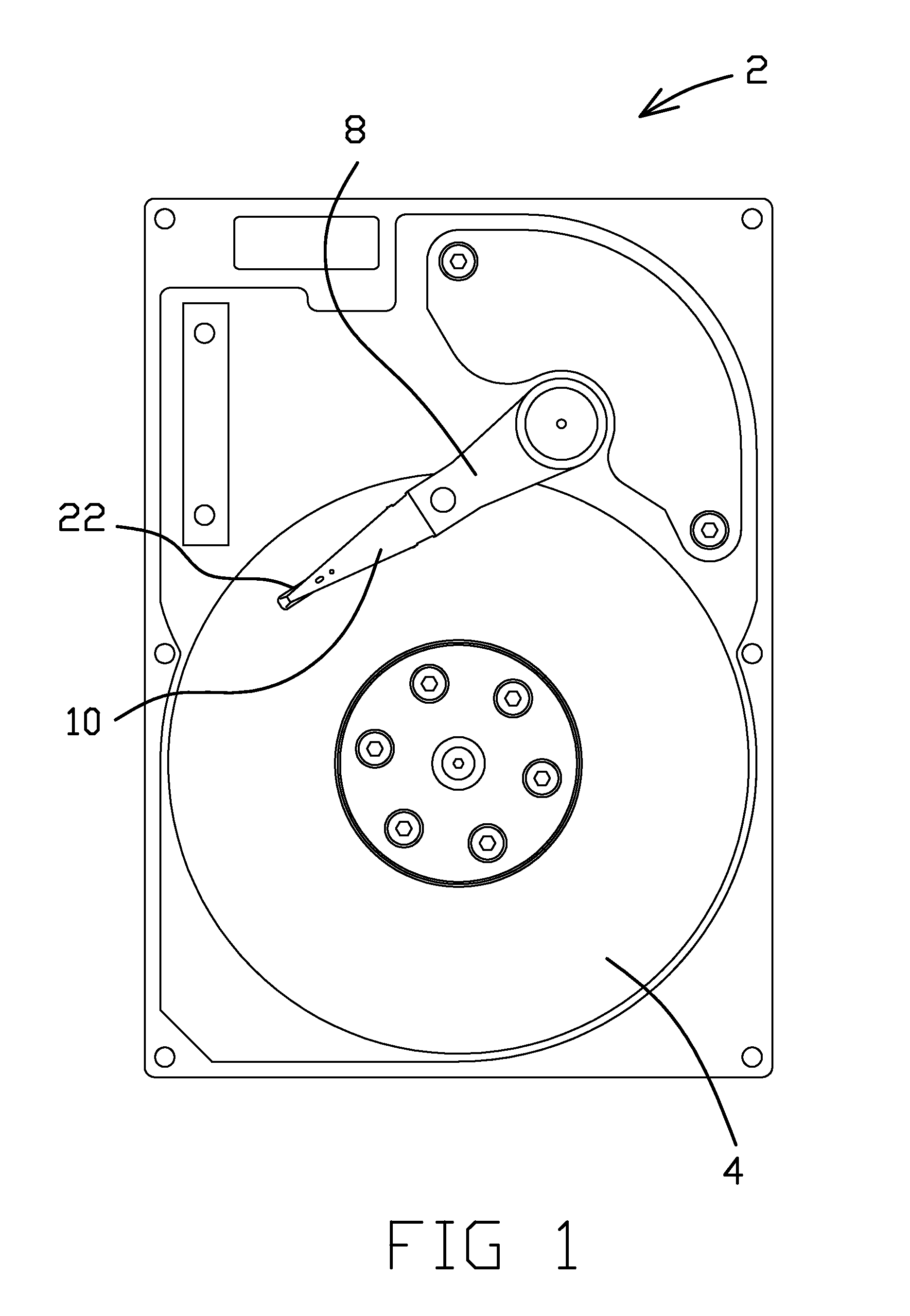
[0037]FIG. 1 shows a plan view of a disk drive 2 having a head suspension 10 suspended over a disk 4. The head suspension 10 supports a slider 22 over the disk 4. The head suspension 10 is attached at its proximal end to an actuator arm 8, which is coupled to an actuator motor 6 mounted within the disk drive 2. The actuator motor 6 positions the actuator arm 8, head suspension 10, and slider 22 over a desired position on the disk 4. In the embodiment shown, the actuator motor 6 is rotary in nature, and operates to radially position the head suspension 10 and slider 22 over the disk 4. Other actuator motors, such as a linear actuator motor, can alternatively be used.

[0038]In use, the slider 22 reads from and / or writes to the disk 4 while the head suspension 10 supports and aligns the slider 22 over a desired location on the disk 4 in response to signals received from a microprocessor (not shown). The disk 4 rapidly spins about an axis, and an air bearing is created by the flow of air...


PUM

PropertyMeasurementUnit
Lengthaaaaaaaaaa
Forceaaaaaaaaaa

Abstract

Various embodiments concern a suspension assembly of a disk drive. The suspension assembly includes a load beam comprising a major planar area formed from a substrate. The load beam further comprises a window in the substrate, a dimple formed from the substrate, and a flange. The flange is a region of the major planar area that extends partially around the dimple but does not extend along an edge of the dimple. The edge of the dimple is adjacent to the window. The dimple is in contact with the flexure. A HAMR block or other element can extend through the window. The lack of a full flange can minimize the necessary clearance between the dimple and the HAMR block or other element and thereby allow the window to be enlarged to accommodate the HAMR block or other element.

Description

CROSS-REFERENCE TO RELATED APPLICATION[0001]This application claims the benefit of U.S. Provisional Application Ser. No. 61 / 846,492 filed on Jul. 15, 2013, and entitled DISK DRIVE SUSPENSION ASSEMBLY HAVING A PARTIALLY FLANGELESS LOAD POINT DIMPLE, which is incorporated herein by reference in its entirety for all purposes.TECHNICAL FIELD[0002]The present disclosure relates generally to a head suspension assembly of a disk drive. In particular, the present invention concerns a load point element having a partial flange.BACKGROUND OF THE INVENTION[0003]Disk drives operate by reading and / or writing data to sections of one or more spinning disks housed within the disk drive. One or more transducers can be moved along each spinning disk to allow the one or more transducers to interface with different areas of the disks in a rapid manner. The one or more transducers are held over the disk by a head suspension assembly. The one or more transducers typically write to, and read from, the dis...

Claims


Application Information

Patent Timeline
IPC IPC(8): G11B5/55
CPCY10T29/49995G11B5/4833G11B5/55G11B5/4826G11B5/48G11B5/4866G11B5/4873G11B2005/0021
Inventor BENNIN, JEFFRY S.DRAPE, RICK R.GLAESER, THOMAS J.HARTMANN, COREY S.MERCER, HAVEN A.NOGA, DANIEL P.
Owner HUTCHINSON TECH
Learn More