Surgical suction wand

a suction wand and suction tube technology, applied in the field of suction devices, can solve the problems of damage to the device, complicated irrigation function, and inability to inhibit larger potentially clogging debris

Active Publication Date: 2014-05-13
STIEHL TECH
View PDF43 Cites 29 Cited by
  • Summary
  • Abstract
  • Description
  • Claims
  • Application Information

AI Technical Summary

Problems solved by technology

The apparatus disclosed in Prusmack is not ideal because the tissue and clot can travel through device all the way to the valve mechanisms, potentially damaging the device.
The irrigation function is complicated as it requires both turning of a stopcock and operation of a button to move the irrigation channel into the main flow path.
Also, it does not inhibit larger potentially clogging debris from being sucked into the device beyond the point where the declogging function can be effective.
As shown in the Prusmack publication, a major obstacle to the optimal performance of sucker wands is the obstruction that occurs when bone bits and other debris are sucked into the suction line, effectively clogging the egress of fluids away from the surgical site and blocking the suction.
A secondary problem has been the relatively high flow of air through the wand during the surgical procedure which leads to the potential deposition of airborne bacteria on the tip of the wand.
And because the wand tip is moistened by the egress of fluid during suction, the wand tends to attract dust or debris which are then expelled to the surgical site when positive pressure is produced.

Method used


Image

  • Surgical suction wand
  • Surgical suction wand
  • Surgical suction wand

Examples


Embodiment Construction

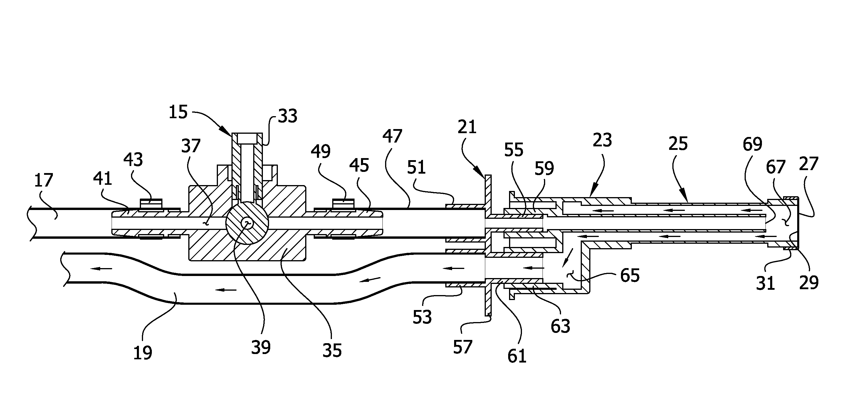
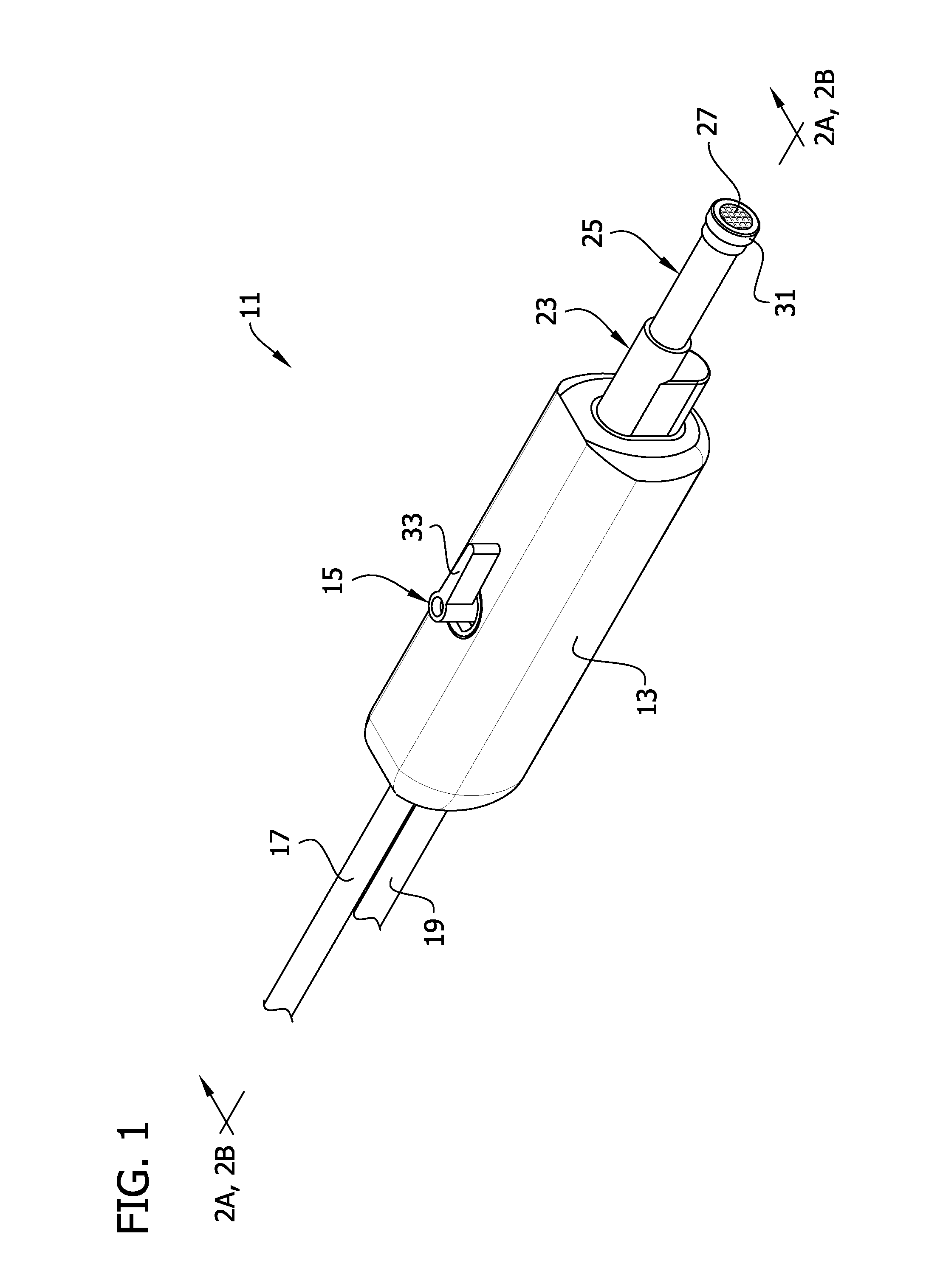
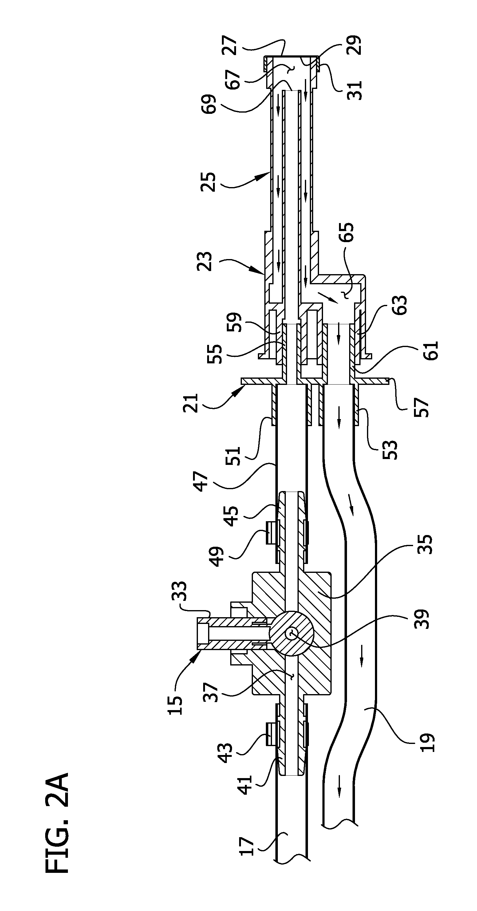
[0022]Referring to the illustrated embodiment, and in particular FIG. 1, a suction wand for use during surgical operation to aspirate a surgical site is generally indicated at 11. The suction wand comprises a handle 13 and a valve generally indicated at 15, partially received in the handle for movement between an open and a closed position. An inflow tube 17 extends proximally from a proximal end of the handle 13 and is configured for attachment to a positive pressure source (not shown). The preferred positive pressure source is a CO2 tank or a line source. An outflow tube 19, below the inflow tube 17, also extends proximally from the proximal end of the handle 13 and is configured for attachment to a negative pressure or suction source (not shown).

[0023]A mount 21 (FIGS. 2A-B) at a distal end of the handle 13 attaches a connector 23 and head portion 25 to the handle. The head portion 25 comprises a tubular member having a filter screen 27 disposed in an open, distal end or tip 29 o...


PUM


Abstract

A suction wand for use during a surgical operation involving cutting of bone which yields bone debris, the wand comprising a suction conduit, a suction tip, and a positive pressure conduit for directing gas toward the suction tip to expel debris.

Description

FIELD OF THE INVENTION[0001]The present invention generally relates to a suction device for use in surgical procedures and more particularly to a surgical suction device for removing debris from a surgery site.BACKGROUND OF THE INVENTION[0002]Suction devices are commonly used in a variety of medical applications to evacuate various fluids from a patient for a variety of purposes. For example, during surgery, blood and other body fluids are commonly removed to permit visual inspection of the surgical site and disposal of fluids. Suction wands may also provide for the production of positive pressure (usually air or water) to irrigate the surgical site. One such example is disclosed in Lester, U.S. Pat. No. 4,526,573 which shows a suction conduit for sucking debris away from the surgery site and an irrigation conduit for directing irrigation fluid to a surgery site.[0003]Prusmack US Publication No. 2007 / 0213667 discloses a suction irrigation cleaner configured to apply negative air pre...

Claims


Application Information

Patent Timeline
Patent Type & Authority Patents(United States)
IPC IPC(8): A61M1/00
CPCA61M1/0056A61M1/0062A61M1/0084A61M2210/02A61M1/00A61M1/79A61M1/85A61M1/772
Inventor STIEHL, JAMES B.STIEHL, KURT R.
Owner STIEHL TECH
Why Eureka
Try Eureka