
Window restrictor

Inactive Publication Date: 2014-05-20
MIGHTON PRODS LTD
View PDF17 Cites 47 Cited by
  • Summary
  • Abstract
  • Description
  • Claims
  • Application Information

AI Technical Summary

Benefits of technology

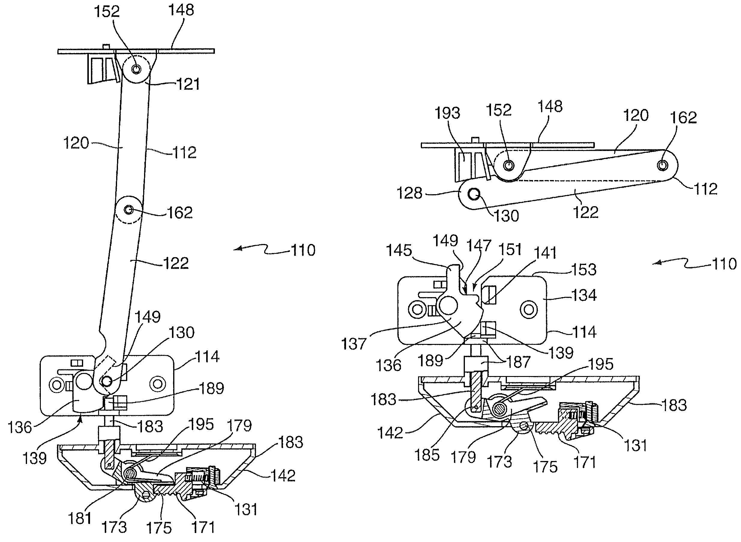
[0024]Preferably in the released and disengaged configuration, the first locking means is urged (or biased) into a position aligned with the second locking means such that subsequent movement of the window towards a closed position may cause the first locking means to be automatically engaged with the second locking means. Preferably this arrangement effectively resets the latching mechanism.
[0049]The latching recess may encapsulate the first locking means in an engaged configuration and prevents any translational movement of the first locking means relative to the latching recess in an engaged configuration. The first locking means may be rotatable relative to the latching recess in an engaged configuration.
[0051]The latching recess may be provided on a latching plate. The latching plate may be rotatable between a first position and a second position. Preferably in the first position the latching plate prevents removal of the first locking means from the second locking means. Preferably in the second position the first locking means is removable from the second locking means.

Problems solved by technology

Such an override mechanism needs to be easily and quickly operable by a user in an emergency but also needs to be complicated enough to prevent the easy operation by a child and to prevent the accidental operation by a person or animal.

Method used


Image

  • Window restrictor
  • Window restrictor
  • Window restrictor

Examples


Embodiment Construction

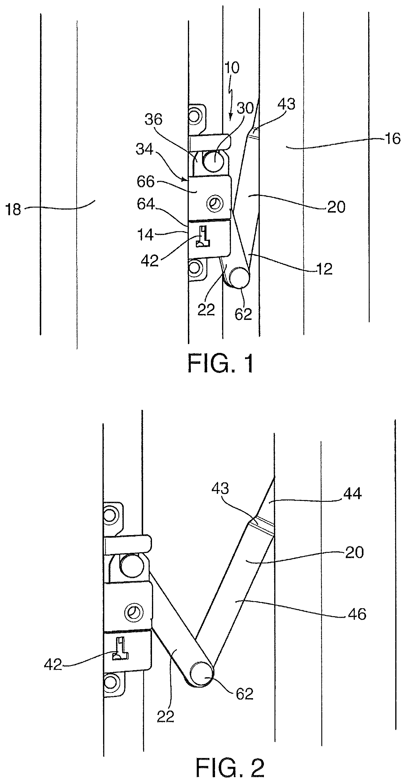
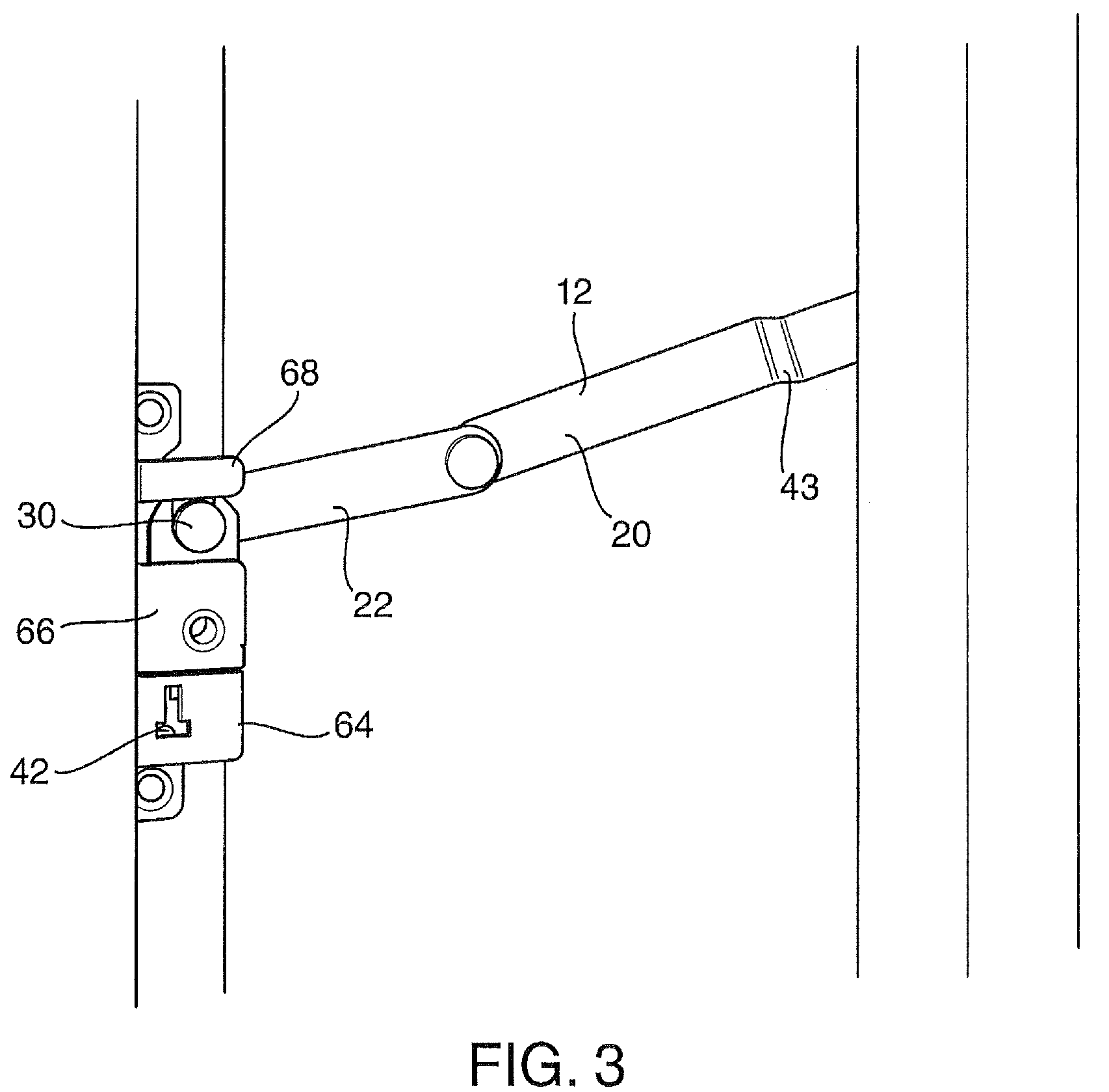
[0102]As shown in FIGS. 1 to 5, the window restrictor 10 of the present invention may be used to limit the opening of a sash (sliding) window or a casement (hinged) window. The restrictor 10 comprises a restrictor member 12 and a latch mechanism 14. Typically, the restrictor member 12 is attached to a stile or rail 16 of the moving window pane and the latch mechanism 14 is attached to a part of the casing or frame 18 surrounding the window opening. In alternative embodiments the restrictor member 12 may be attached to the frame 18 and the latch mechanism 14 may be attached to the rail 16.

[0103]In use, the restrictor member 12 is engaged with the latch mechanism 14 so that as the window is opened, the extent of opening is restricted by the length of the restrictor member 12. To fully open the window, the restrictor member 12 must be disengaged from the latch mechanism 14.

[0104]A main advantage of the restrictor 10 of the present invention is that, when the restrictor member 12 and la...


PUM

PropertyMeasurementUnit
relative movementaaaaaaaaaa
movementaaaaaaaaaa
translational movementaaaaaaaaaa

Abstract

A window restrictor that may be used to limit the opening of a window. The restrictor comprises a restrictor member and a latch mechanism. Typically, the restrictor member is attached to a stile or rail of the moving window pane and the latch mechanism is attached to a part of the casing or frame surrounding the window opening. In use, the restrictor member is engaged with the latch mechanism so that as the window is opened, the extent of opening is restricted by the restrictor member length. To fully open the window, the restrictor member is disengaged from the latch mechanism. When the restrictor member and latch mechanism are disengaged, they remain in such a configuration that, when the window is closed, the restrictor member and latch mechanism automatically re-engage to prevent the window being fully opened again. The restrictor member can comprise a hinged member which includes bias means.

Description

FIELD OF THE INVENTION[0001]This invention relates to a device for limiting or restricting the extent of opening of a window, and may be applicable to both sash and casement windows.BACKGROUND TO THE INVENTION[0002]There is a requirement to restrict the extent to which a sash or casement window can be opened, partly to prevent children opening a window beyond a certain distance so that they cannot fall out through the window, and partly from an anti-theft point of view, to prevent the window being opened from the outside.[0003]However any such restrictor needs to be capable of being overridden when the window is to be fully opened by an adult, from the inside. Such an override mechanism needs to be easily and quickly operable by a user in an emergency but also needs to be complicated enough to prevent the easy operation by a child and to prevent the accidental operation by a person or animal.[0004]It is an object of the present invention to overcome at least one problem associated w...

Claims


Application Information

Patent Timeline
Patent Type & Authority Patents(United States)
IPC IPC(8): E05B65/10
CPCE05C17/32E05C17/08E05B65/0014E05C19/003Y10T292/304Y10T29/49826E05B1/0038
Inventor DERHAM, MICHAEL
Owner MIGHTON PRODS LTD
Learn More