
Power supply system for electronic loads

a technology of power supply system and electronic load, applied in the direction of electric variable regulation, process and machine control, instruments, etc., can solve the problems of inconvenient operation and erroneous operation, and achieve the effect of high additional losses

Inactive Publication Date: 2014-07-08
KONINKLIJKE PHILIPS ELECTRONICS NV
View PDF5 Cites 0 Cited by
  • Summary
  • Abstract
  • Description
  • Claims
  • Application Information

AI Technical Summary

Benefits of technology

The present invention aims to provide a solution for adapting power supply systems to different grids without requiring expensive components. The solution involves the use of different connector devices for connecting a converter circuit to the grids. One of these connector devices includes a transformation circuit that transforms the voltage to match the output voltage of the other connector device, thus ensuring proper adaptation of voltages. The use of dedicated converters for voltage transformation helps to minimize hardware and cost efforts for the different connector devices. The invention also provides for manipulating voltage levels through the use of polarity-dependent switches, such as diodes and transistors, to avoid energy losses and bulky components. The technical effect of the invention is to enhance the flexibility and adaptability of power supply systems for different grids.

Problems solved by technology

This is not convenient but prone to erroneous operation.

Method used


Image

  • Power supply system for electronic loads
  • Power supply system for electronic loads
  • Power supply system for electronic loads

Examples


Embodiment Construction

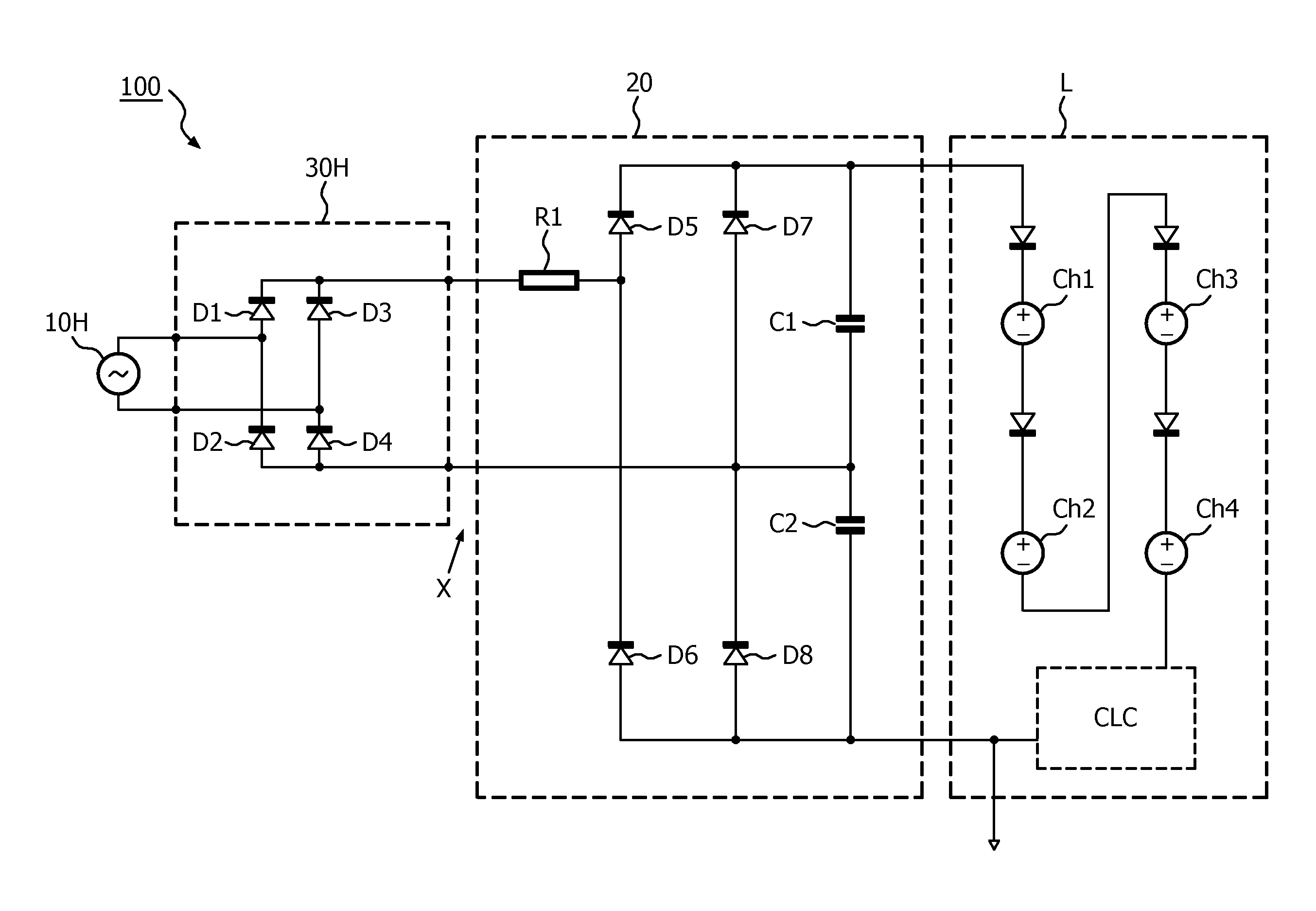
[0039]The power supply system and the method according to the invention will in the following be explained with reference to a luminaire, though its application is not limited to this case. Instead, the principles and the circuits can be applied with other loads that shall be operated with different grid voltages, too. In particular, the invention can be applied for loads requiring a DC power supply that shall be operated with AC voltages from the US and European grid, respectively.

[0040]For luminaires for the customer market, there is the wish to have one product design that can be used world-wide. This requirement includes the need to be independent from different mains voltage values (e.g. 115 V in the US and 230 V in Europe). On the other hand, LEDs are becoming a standard, non-replaceable component which will be used in a variety of luminaires due to their long lifetime. Due one addressed market, the consumer market, it is desired to have a system which does not require user in...


PUM


Abstract

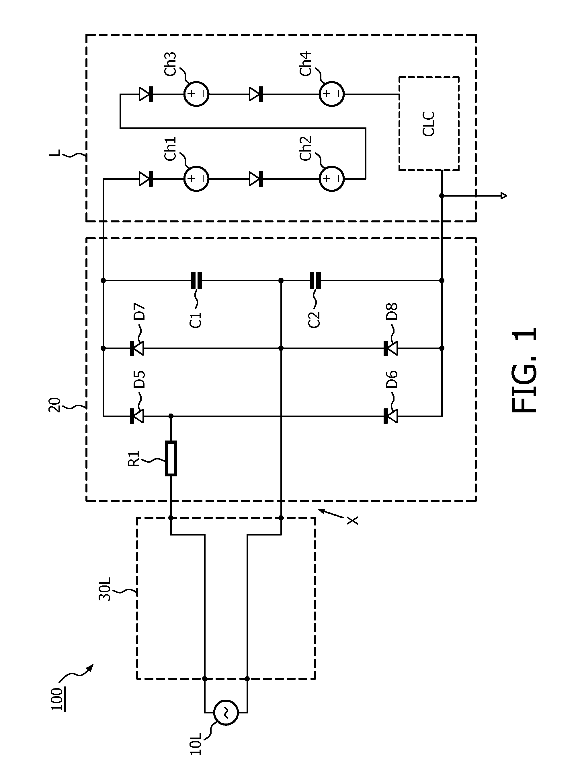
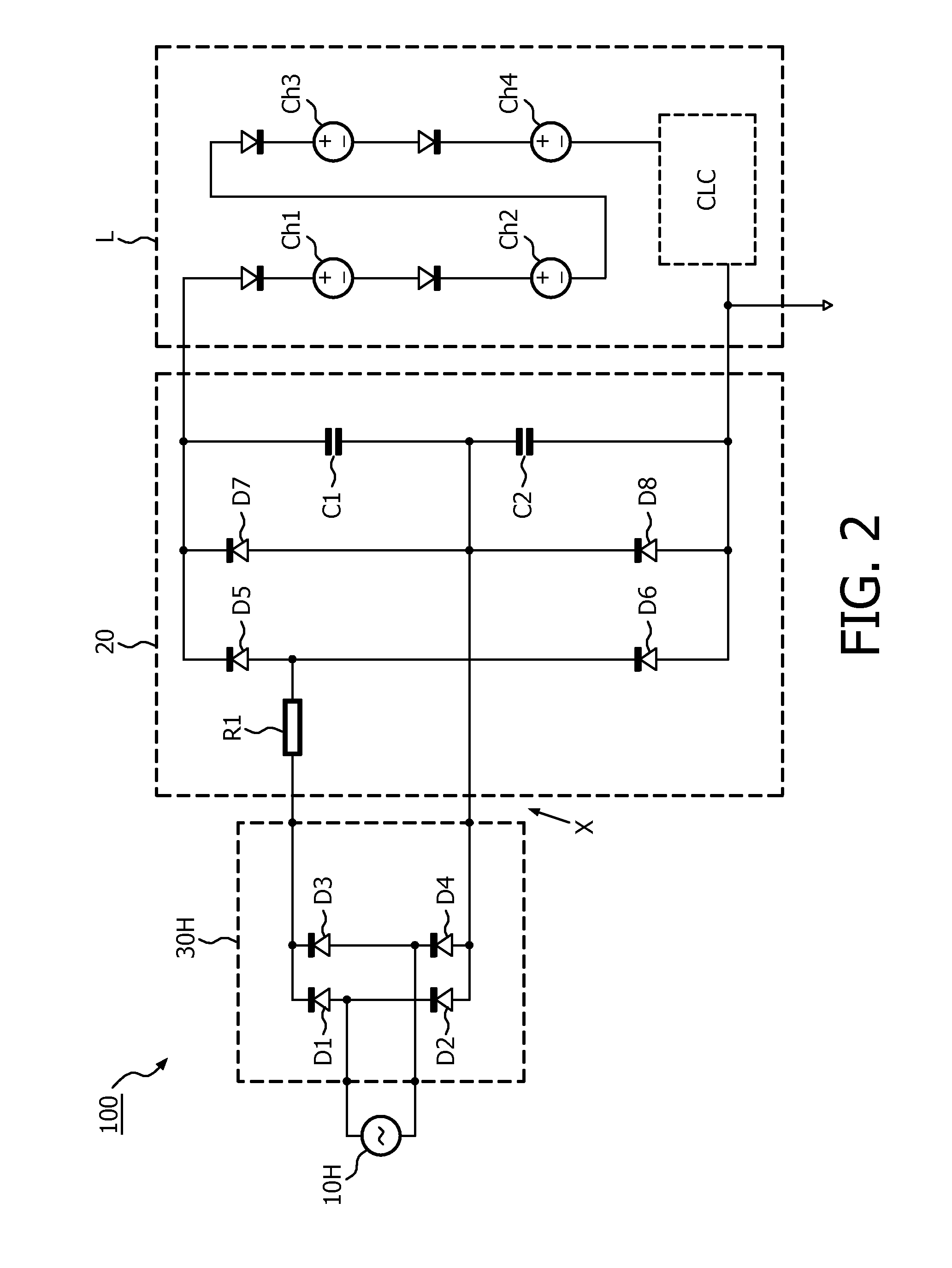
The invention relates to a power supply system and a method for providing a load (L) with electrical power from either a first or a second AC grid source (10L, 10H) that supply different first and second AC voltages, respectively. In a particular example, said grid sources may belong to the US and the European mains, respectively, and the load may be a lamp with mains compatible LEDs (Ch1-Ch4). The power supply system comprises a first and a second connector device (30L, 30H) for connecting a converter circuit (20) to the first or the second AC grid source (10L, 10H), respectively. Moreover, the second connector device (30H) comprises a transformation circuit (D1-D4) for transforming the second AC voltage such that it yields a similar output voltage of the converter circuit (20) as the first AC voltage. In a particular example, the converter circuit (20) may comprise a rectifier (D5-D8, C1, C2) with voltage doubling function, and the second connector device (30H) may comprise a rectifier (D1-D4) while the first connector device (30L) is a simple cable.

Description

FIELD OF THE INVENTION[0001]The invention relates to a power supply system and a method for providing a load with electrical power from different AC grid sources. Moreover, it relates to a luminaire comprising such a power supply system.BACKGROUND OF THE INVENTION[0002]Most electric or electronic devices are operated with electrical power taken from the public electricity grid (shortly called “grid” or “mains” in the following). As the grids of different countries provide different AC voltages, for example about 115 V in the USA and about 230 V in Europe, provisions have to be taken that allow the adaptation of a device to such different voltage supplies. From the EP-0531995 A2, a circuit is for example known in which the user has to close or open a switch depending on the grid the associated apparatus shall be connected to. This is not convenient but prone to erroneous operation.SUMMARY OF THE INVENTION[0003]Based on this background it was an object of the present invention to prov...

Claims


Application Information

Patent Timeline
Patent Type & Authority Patents(United States)
IPC IPC(8): H05B41/16H05B44/00
CPCY10T307/675H05B33/0809H02M1/10H05B45/37Y02B20/30H02H7/1216Y02T10/72
Inventor RADERMACHER, HARALD, JOSEF, GUNTHER
Owner KONINKLIJKE PHILIPS ELECTRONICS NV
Learn More