Transmission of motorcycle

a technology for transmission and motorcycles, applied in the direction of toothed gearings, gearing elements, gearings, etc., can solve the problems of increasing the number of operational rotations the inability of the rider to obtain a stable operation feeling, and the difference in rotational speeds between the friction ring and the member between which the friction ring is located, so as to improve the durability of the friction ring and ensure the operation. the effect of stable gear shift operation feeling

Active Publication Date: 2014-07-15
SUZUKI MOTOR CORP
View PDF5 Cites 3 Cited by
  • Summary
  • Abstract
  • Description
  • Claims
  • Application Information

AI Technical Summary

Benefits of technology

[0019]Disclosed embodiments provide a transmission of a motorcycle capable of giving a stable gear shift operation feeling to a rider and improving durability of a friction ring by making the rotation resisting force constant even in gear shift operation to any gear position by suppressing the number of operational rotations of the friction ring.

Problems solved by technology

Therefore, rotational speeds of the dog pieces composing the dog clutch are also different from each other, thus causing a shift shock in a case when the dog pieces with different rotational speeds are meshed with each other, thus being inconvenient.
In the conventional technology such as mentioned above, for example, when slowing down the counter shaft using the friction ring, there occurs a problem of causing a difference of rotational speeds between members between which the friction ring is interposed.
Accordingly, there causes a problem such that when the friction ring is arranged between the counter shaft and the fifth drive gear as in the above-described conventional example, a rotation resisting force differs for every gear shift operation depending on the each selected gear position, and in such occasion, a rider cannot obtain a stable operation feeling.
Accordingly, in the arrangement in which the friction ring is arranged between the counter shaft and the fifth drive gear as in the above-described conventional example, the number of operational rotations of the friction ring in the low gear positions is increased, and in a case when a particularly large friction torque is required, an inconvenient matter will occur in durability of the friction ring.

Method used


Image

  • Transmission of motorcycle
  • Transmission of motorcycle
  • Transmission of motorcycle

Examples


Embodiment Construction

[0052]Disclosed embodiments will be described hereinafter with reference to the accompanying drawings.

[0053]It is further to be noted that terms “upper”, “lower”, “right”, “left” and other like terms representing directions or positions are used herein with reference to the illustration of the drawings or in a state of a motorcycle shown in FIG. 1.

[0054]A first disclosed embodiment will be described hereunder.

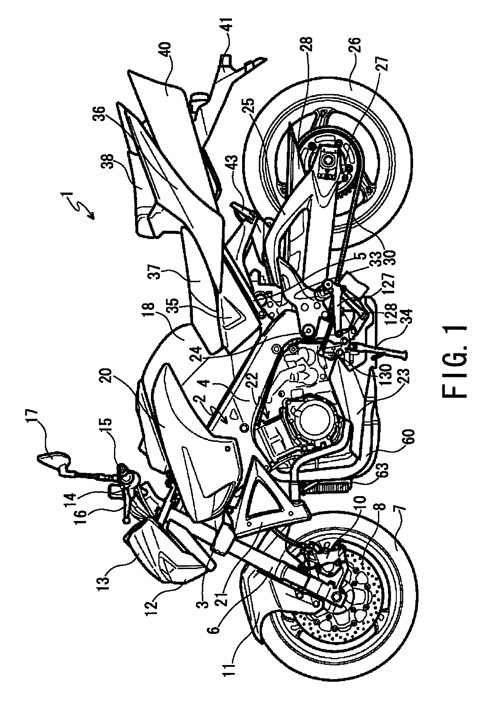
[0055]FIG. 1 shows an entire configuration of a motorcycle 1 to which the first disclosed embodiment is mounted.

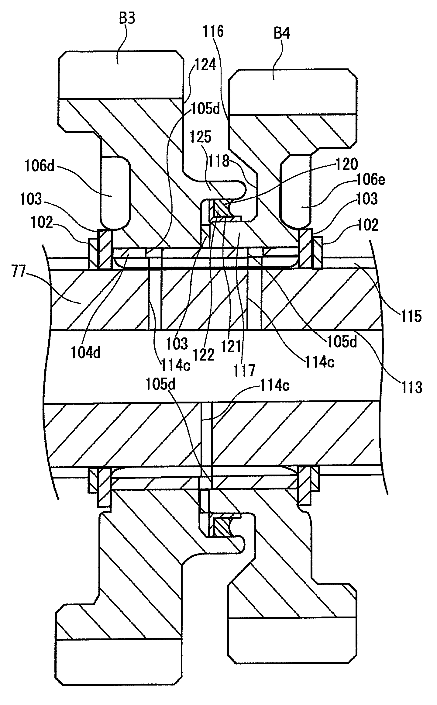
[0056]In FIG. 1, a motorcycle 1 has a vehicle body frame 2 constituting a framework thereof is provided in the motorcycle 1. This vehicle body frame 2 is, for example, a twin-tube type frame, which mainly comprises: a head pipe 3 arranged at a front upper end of the body frame 2; a lateral pair of right and left main frames 4 extending from the head pipe 3 toward a rear lower side; and a pair of right and left seat rails 5 extending from a rear portion of the main fra...


PUM


Abstract

A motorcycle having a transmission which includes a counter shaft to which a rotation of a crankshaft disposed in an engine is transmitted and a drive shaft to which a rotation of the counter shaft is transmitted. A pair of drive gears mounted on the counter shaft so as to be rotated integrally with the counter shaft, and a pair of driven gears mounted on the drive shaft so as to be meshed with the pair of drive gears, respectively, to be rotatable therewith, and a friction ring is interposed between the pair of driven gears.

Description

PRIORITY CLAIM[0001]This patent application claims priority to Japanese Patent Application No. 2010-291651, filed 28 Dec., 2010, the disclosure of which is incorporated herein by reference in its entirety.BACKGROUND[0002]1. Field[0003]Disclosed embodiments relate to a transmission of a motorcycle.[0004]2. Related Art[0005]Generally, a transmission of a motorcycle includes a counter shaft to which a rotation of a crankshaft provided in an engine is transmitted through a clutch, and a drive shaft to which a rotation of the counter shaft is transmitted. When the drive shaft is rotated, the rotation thereof is transmitted to the drive shaft to thereby enable the motorcycle to run.[0006]A plurality of drive gears are mounted on the counter shaft, and a plurality of driven gears always meshed with the drive gears are also mounted on the drive shaft.[0007]In addition, the driven gears are rotatably mounted on the drive shaft in a gear change stage (i.e., speed shift stage) at which the dri...

Claims


Application Information

Patent Timeline
Patent Type & Authority Patents(United States)
IPC IPC(8): F16H3/089F16H3/08F16H61/04
CPCY10T74/19219Y10T74/19358F16H3/089F16H2003/0811F16H61/04F16H2061/0474Y10T74/19284
Inventor YAMAZAKI, MASATO
Owner SUZUKI MOTOR CORP
Why Eureka
Try Eureka