Boat anchor

a technology for anchors and boats, applied in the field of boat anchors, can solve the problems of difficult transportation, and affecting the safety of anchors, and achieve the effects of preventing fouling of anchor lines, facilitating connection and disconnection, and quick and easy setting

Inactive Publication Date: 2014-10-28
PAUGH JOSH
View PDF16 Cites 4 Cited by
  • Summary
  • Abstract
  • Description
  • Claims
  • Application Information

AI Technical Summary

Benefits of technology

[0006]The present invention is directed to an improved detachable boat anchor comprising of two substantially identical plates having two flukes on each of its two opposed sides. A hollow shank is inserted into the housing located on the bottom central surface of the first plate on one end and to another housing located on the top central surface of the second plate on the other end. The shank is secured to the housing by means of a resilient leaf spring with engagement pin to provide an easy connect and disconnect feature of the boat anchor assembly. The flukes are angled upward at the distal end in relation to its respective plates. The fixed flukes design of the anchor allows it to quickly and easily sets itself in a variety of bottom conditions such as sand, mud, rock, or grass. A lead arm is provided to connect an anchor line to the anchor and to prevent fouling of the anchor line.
[0007]The anchor of the present invention does not have any hinge or other moving parts that can jam or foul or present problems of corrosion and poor operation at the hinge as well as potential hazard to the user who handles and works with the anchor. The simple design, minimum number of parts and rigid construction of the anchor presented in the current application means that the anchor presented herein can be manufactured economically and is durable or long lasting, thus providing a good value for the money.
[0008]In view of the above disclosure, it is an object of the present invention to provide a boat anchor that can be quickly assembled for use and easily detachable for compact storage.
[0009]Another object of the invention is to provide a boat anchor that is lightweight, portable and effective in various bottom conditions.

Problems solved by technology

Once the anchor lands on the bottom, a pull on the chain will generally tends to cause the fluke to digs into the bottom.
The traditional anchor types are made in one piece and are generally bulky and heavy making it hard to transport and present a problem for storage.

Method used


Image

  • Boat anchor
  • Boat anchor
  • Boat anchor

Examples


Embodiment Construction

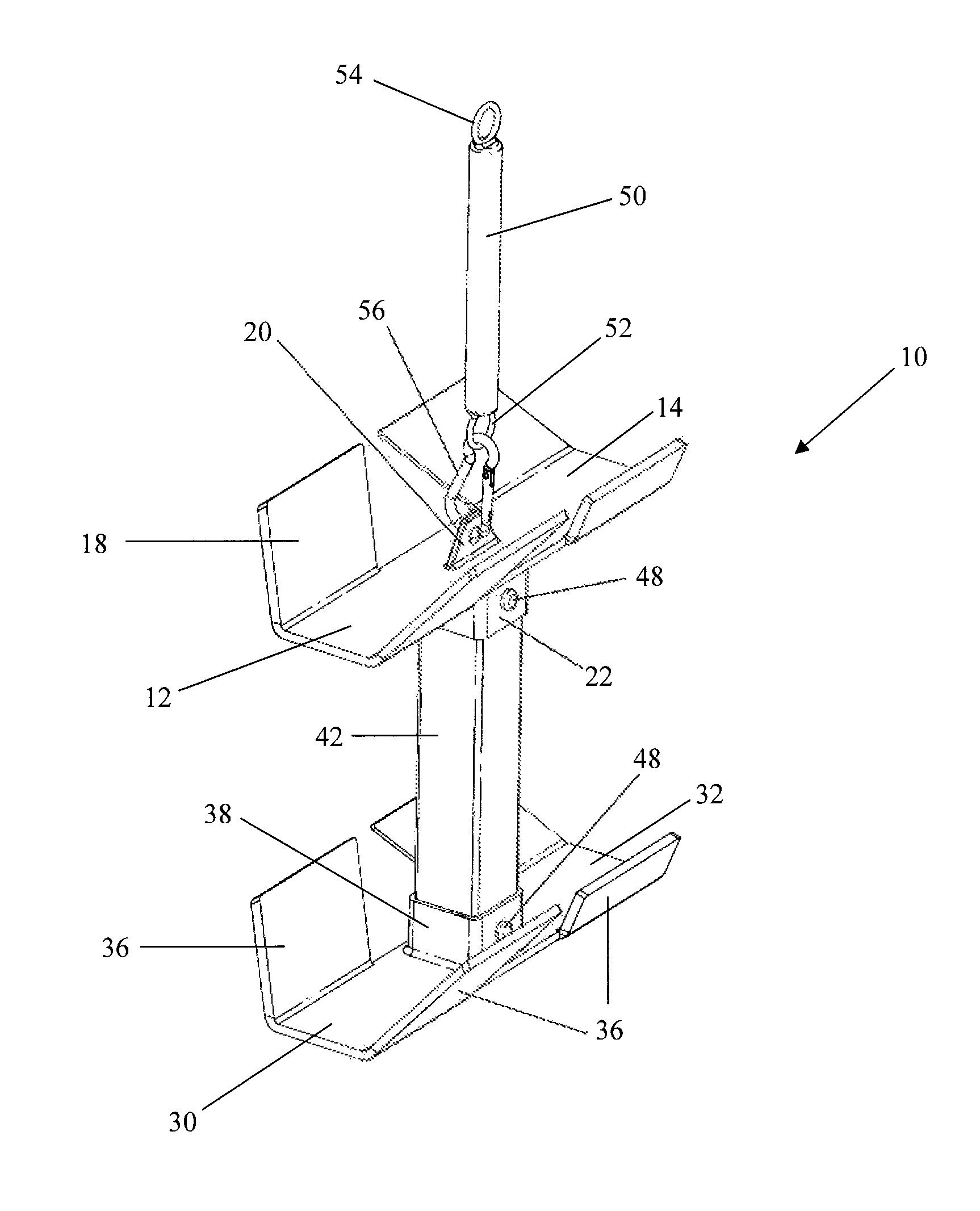
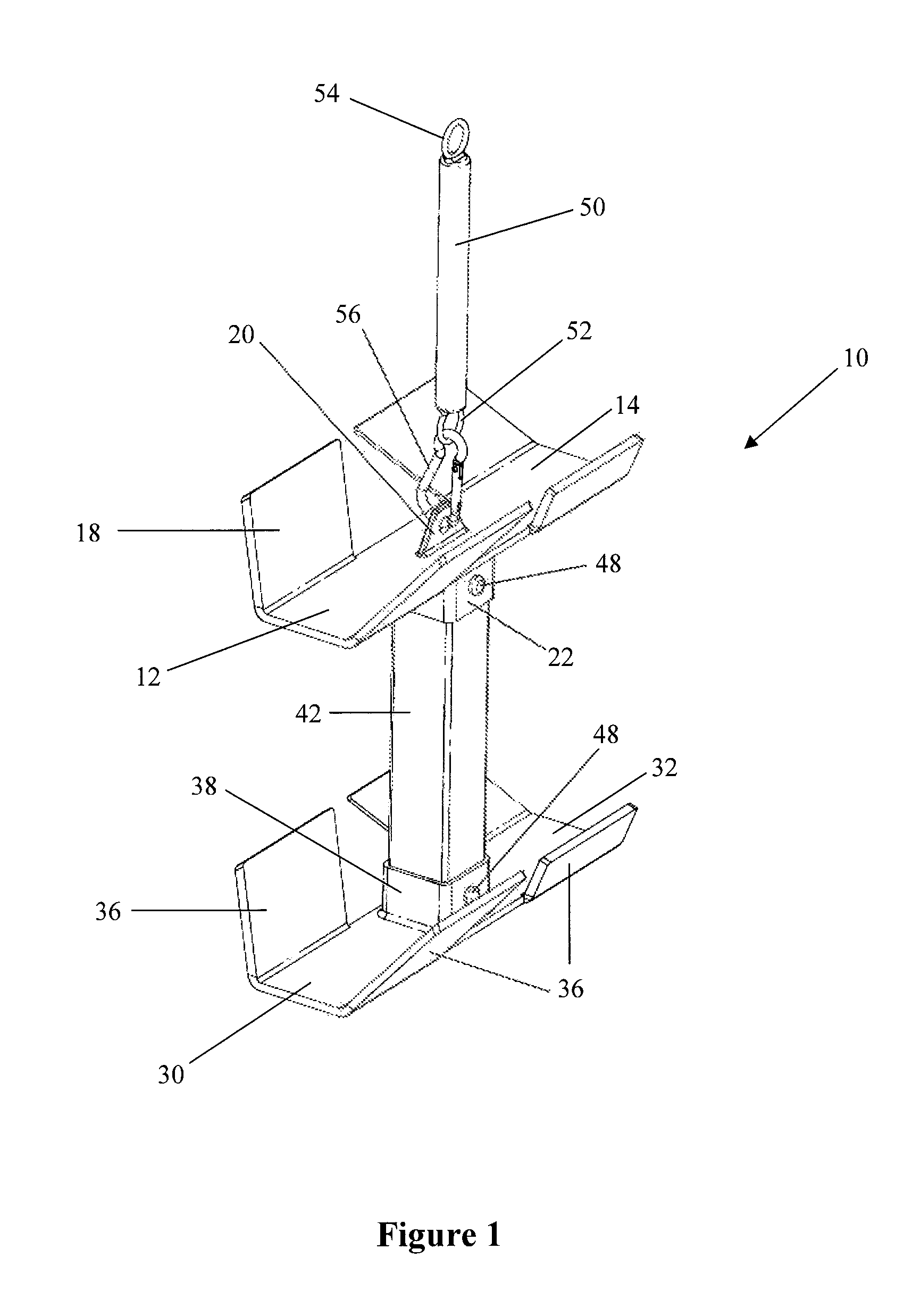
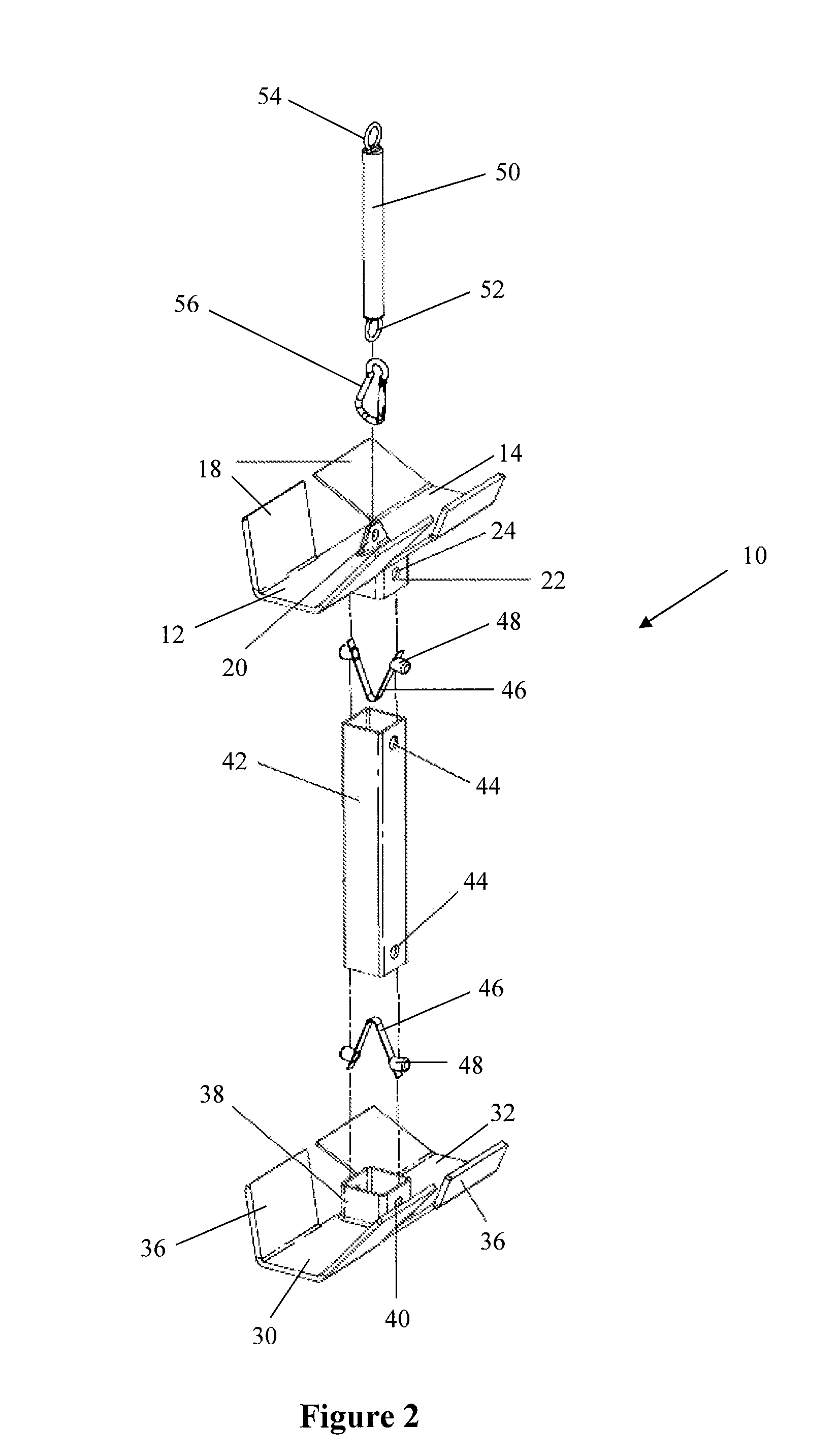
[0017]The best mode of carrying out the invention is presented in terms of a preferred embodiment of a boat anchor 10 as shown in FIG. 1-5. The boat anchor according to the present invention comprises of a first rectangular plate 12 having a top surface 14, a bottom surface 16 and one or more flukes 18 on each of its long sides, and a second rectangular plate 30, substantially identical to the first plate 12, having a top surface 32, a bottom surface 34 and one or more flukes 36 on each of its long sides. A centrally located shank 42 is used to connect the first plate 12 to the second plate 30. The first plate 12 is shown in FIG. 1-3 with an anchor pull ring 20 attached to the top central surface 14 and a housing 22 protruding from the bottom central surface 16. The second plate 30 is shown in FIG. 1-3 with a housing 38 protruding from the top central surface 32. The preferred shape of the plate 12 and 30 would be of a rectangle while the shank 42 would be of an elongated rectangula...


PUM


Abstract

A detachable boat anchor comprises of a first plate having a housing on the bottom central surface and a second plate having a housing on the top central surface. The two plates are connected by a central shank by means of a leaf spring with engagement pin. The shank has two open ends with radial holes formed therethrough proximate to the open ends. The housing has an open end and radial holes formed therethrough and is shaped to receive the shank in a mating relationship to provide a snug fit such that when the radial holes of the shank and the radial holes of the housing are aligned, the engagement pin protrudes from the radial holes to prevent disengagement.

Description

TECHNICAL FIELD[0001]The present invention relates generally to boat anchors and more particularly to a boat anchor that can be quickly assembled for use and easily disassembled for compact storageBACKGROUND OF THE INVENTION[0002]An anchor is a device that is attached to a vessel and dropped into the bottom of a body of water to prevent or restrict the vessel or other floating objects from drifting due to wind or current. Anchors typically achieve holding power either by hooking into the bottom or via sheer mass, or a combination of the two. The vessel is attached to the anchor by an anchor line which is made of chain, cable, rope or a combination of these. The earliest anchors were probably rocks. In ancient times, people used basket of stones, and large sacks filled with sand. Such anchors held the vessel merely by their weight and by their friction along the bottom. Iron was afterwards introduced for the construction of anchors, and an improvement was made by forming them with fl...

Claims


Application Information

Patent Timeline
Patent Type & Authority Patents(United States)
IPC IPC(8): B63B21/24
CPCB63B21/243B63B21/24
Inventor PAUGH, JOSH
Owner PAUGH JOSH
Why Eureka
Try Eureka