Apparatus for distributing a fragrance using a fan

a technology for diffusers and fragrances, applied in the direction of secondary air addition to fuel, combustion air/fuel air treatment, liquid fuel engine components, etc., can solve the problems of relatively high cost, short-lived, and inability to select one of a multiple of fragrances remotely from a dispenser

Inactive Publication Date: 2014-10-28
SCOLARI NATHAN A
View PDF3 Cites 11 Cited by
  • Summary
  • Abstract
  • Description
  • Claims
  • Application Information

AI Technical Summary

Problems solved by technology

With all of these products, a number of drawbacks exist.
With all of these products, however, the benefits are relatively expensive and short-lived.
However, none of these prior attempts include the ability to select one of a multiple of fragrances remotely from a dispenser when such dispenser is located out of reach, such as when installed on a ceiling fan.

Method used


Image

  • Apparatus for distributing a fragrance using a fan
  • Apparatus for distributing a fragrance using a fan
  • Apparatus for distributing a fragrance using a fan

Examples


first embodiment

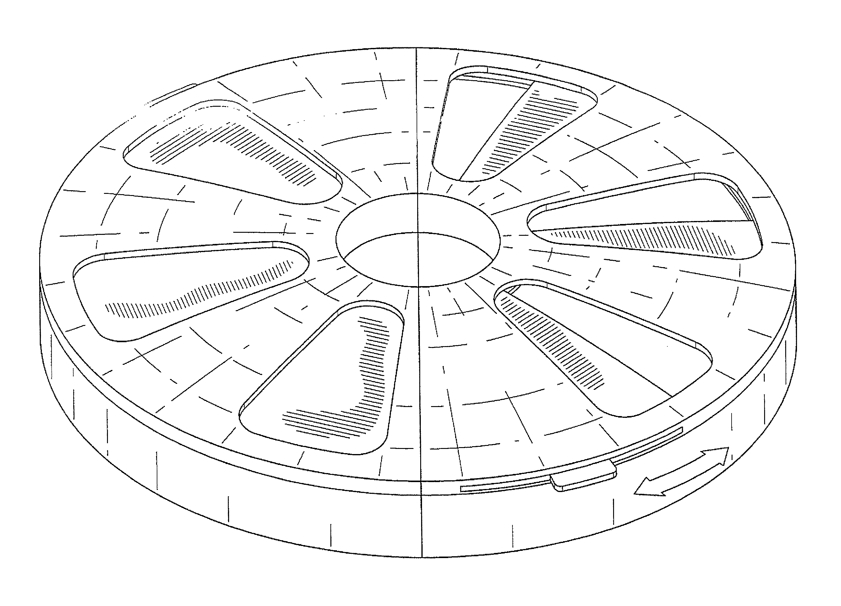
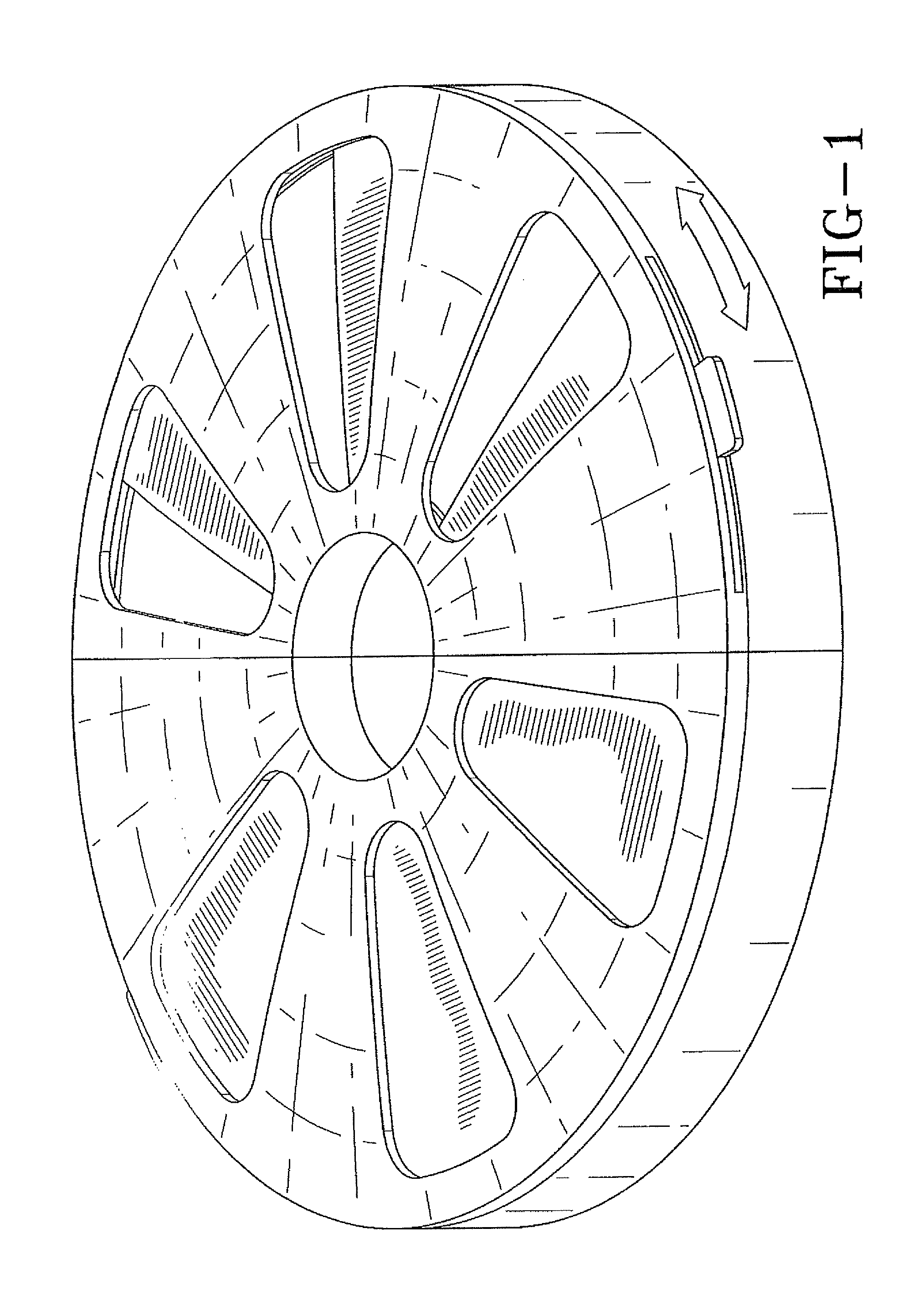
[0033]A fragrance releasing element is located in each semi-circular housing member. The fragrance releasing element may, for example, be a fibrous pad that serves as a permeable substrate to which a fragrant material is applied, or a porous bag that contains fragrance releasing spheres, granules or the like. The fragrances released from each of the semi-circular housing members can be the same or, if desired, the fragrances released from the semi-circular housing members may be different. If the shutters are both moved to a position such that the vent openings in the tops of the housing members are closed, only a minimal amount of fragrance may escape from the fragrance dispenser. However, when the shutters are both moved to positions such that the vent openings in the top of the housing members are fully opened, a maximum amount of fragrance escapes from the fragrance dispenser when the fan is operating. The amount of fragrance released may be further varied by adjusting the openi...

third embodiment

[0037]While the first two embodiments of a fragrance dispenser for use with a ceiling fan are designed to be retrofitted to a previously installed ceiling fan, a fragrance dispenser can also be installed as a part of the installation of a ceiling fan, and could either be sold separately or as a part of a ceiling fan kit. A fragrance dispenser of this third embodiment comprises a circular housing member having a top, a bottom, a circumferentially extending outer sidewall, and a circumferentially extending inner sidewall that surrounds a circular passage for receiving the down rod of a ceiling fan.

[0038]FIGS. 8 and 9 show a fragrance dispenser to be mounted to a box fan.

[0039]FIG. 10 shows a fragrance dispenser to be mounted to a pedestal fan.

[0040]Referring now to FIG. 13, another embodiment is described. A fragrance container 10 is carried by a housing 12. The container can receive fragrance pads, cloth, blocks, solid, liquids, or other fragrance dispensing material through opening ...


PUM

PropertyMeasurementUnit
areaaaaaaaaaaa
distancesaaaaaaaaaa
heightsaaaaaaaaaa

Abstract

This application is directed to a fragrance dispenser attachably connected to a fan comprising: a housing having openings defined in the housing; a fragrance reservoir included in the housing for receiving a fragrance medium containing a fragrance; a cover operably associated with the opening for restricting airflow into the fragrance reservoir; and, a cover actuator operably connected to the cover having an open position allowing airflow into and out of the fragrance reservoir for dispensing a fragrance and a closed position for restricting airflow into and out of the fragrance reservoir.

Description

CLAIM OF PRIORITY[0001]This application claims priority on U.S. Provisional Patent Application Ser. No. 61 / 439,618 filed Feb. 4, 2011.FIELD OF THE INVENTION[0002]This invention is directed to an apparatus for distributing fragrances using a fan, and more particularly, to an apparatus having multiple fragrances that can be selected by a user for distribution.BACKGROUND OF THE INVENTION[0003]There is a large market for various products used to mask and control unwanted odors in homes and work placed, or to enhance the air in a home or work place. Such products typically include air freshener sprays, blocks, electrically operated scent dispensers, candles, wicks, potpourri and the like. With all of these products, a number of drawbacks exist. With sprays, it is necessary to dispense the spray by hand in each room or area where the odor control is desired. With wicks, blocks, plug-in devices and the like, a number of them must be placed throughout the space in which the odor control is ...

Claims


Application Information

Patent Timeline
Patent Type & Authority Patents(United States)
IPC IPC(8): A61L9/03A61L9/12B01F3/04
CPCY10S261/88A61L9/032Y10S261/89A61L9/122A61L9/127F04D29/00
Inventor SCOLARI, NATHAN, A.
Owner SCOLARI NATHAN A
Why Eureka
Try Eureka