Secondary air injection system for an internal combustion engine

a technology of air injection system and internal combustion engine, which is applied in the direction of engine components, machines/engines, mechanical equipment, etc., can solve the problems of low end torque loss, low efficiency, cost and complexity, and achieve the effect of less costly and complex manufacturing and improved operating characteristics

Inactive Publication Date: 2009-04-14
VOLVO CAR CORP
View PDF12 Cites 6 Cited by
  • Summary
  • Abstract
  • Description
  • Claims
  • Application Information

AI Technical Summary

Benefits of technology

[0007]Accordingly, the present invention is directed to providing an improved arrangement in a secondary air injection system for an internal combustion engine, which is potentially less costly and complex to manufacture and has improved operating characteristics.
[0009]The invention is of advantage in that inclusion of the reed-type non-return valves reduces the complexity and eliminates the need of more than one shut-off valve, which elimination and the fact that the reed-type non-return valves generally are less expensive reduces the overall cost of the secondary air injection system.
[0011]Providing separate exhaust banks for each separate exhaust port of said internal combustion engine will substantially reduce the occurrence of “breathing” between exhaust banks and / or individual exhaust ports, thus improving low end torque characteristics.
[0013]This is advantageous as reed-type non-return valves may otherwise have a tendency to “flutter”, i.e. oscillate between closed and open position, which in addition to being unsatisfactory from a performance point of view contributes to decreasing the service life expectancy of the reed-type non-return valves, e.g. due to materials fatigue. Due to the under pressure the reed-type non-return valves will remain closed until the shut-off valve is opened next time.
[0015]Arranging the flexible connector to thermally separate the valve from the reed-type non-return valves imparts to the secondary air injection system other desirable characteristics in addition to those mentioned above, in particular the connector will enable the thermal separation of the valve from the exhaust banks, enabling the valve to be assembled from less expensive materials possibly less able to withstand the high temperatures associated with the exhaust banks, which further reduces the overall cost of the secondary air injection system. Furthermore, from a packaging point of view, increased flexibility is provided for.
[0017]Utilising as the flexible connector a hose, such as a rubber hose, will further contribute to maintaining a low overall cost of the secondary air injection system, while ensuring the positive properties mentioned above as well as ease of servicing and maintenance.

Problems solved by technology

A technical problem encountered with the secondary air injection systems described in the foregoing is that although the above-mentioned arrangement results in a reduced time taken until the so-called “light-off temperature” of the catalyst is reached, it suffers from the drawback that the performance of the engine is easily negatively affected.
This is among other things due to the fact that so-called “breathing” between the cylinders of the internal combustion engine tends to occur, resulting in low end torque loss.
However, in order to reduce the cost and complexity of such a secondary air injection system usually a common secondary air injection pump is used, the air of which is then selectively fed into the respective exhaust banks using a respective complex and rather expensive shut-off valve.
This tends to further increase the cost of the shut-off valves.

Method used


Image

  • Secondary air injection system for an internal combustion engine
  • Secondary air injection system for an internal combustion engine
  • Secondary air injection system for an internal combustion engine

Examples


Embodiment Construction

)

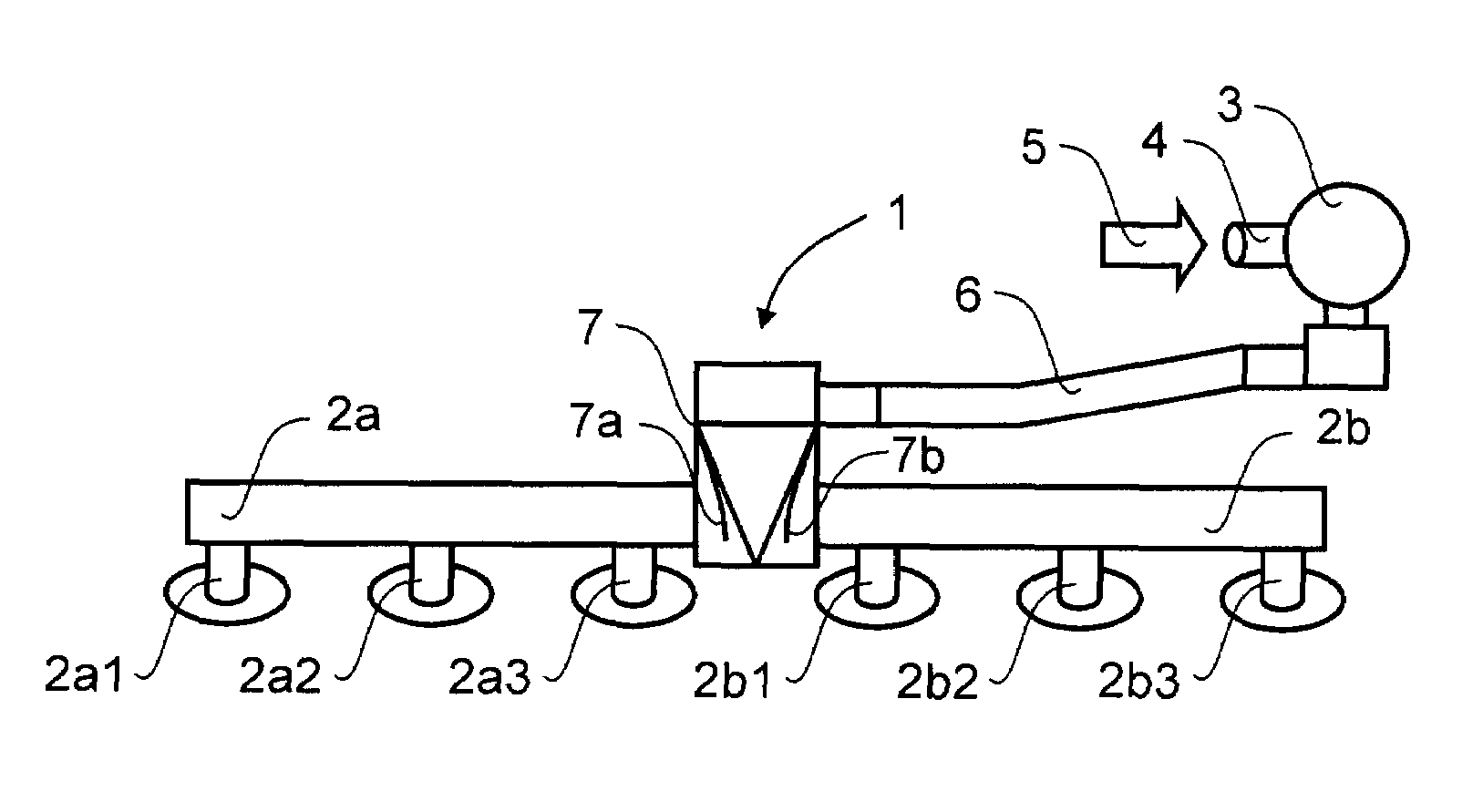
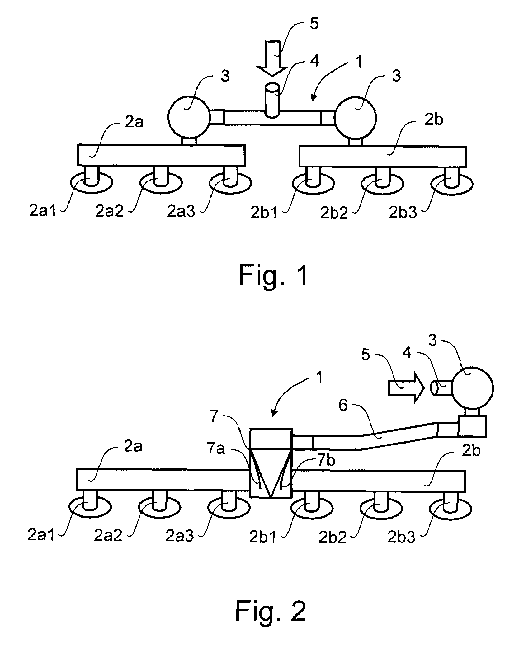
[0024]Referring to FIG. 1, there is illustrated schematically a previously known way of addressing the problem of so-called “breathing” between the cylinders of an internal combustion engine in a secondary air injection system generally designated 1. The proposed solution has been to separate the exhaust banks 2a, 2b of the cylinders (not shown) that are likely to cause this problem and to inject secondary air into the exhaust gas of the respective exhaust banks 2a, 2b separately. In FIG. 1 this is illustrated for a six cylinder engine being provided with two exhaust banks 2a and 2b, serving e.g. cylinders 1-3 and 4-6 through connecting pipes 2a1, 2a2, 2a3 and 2b1, 2b2, 2b3 respectively.

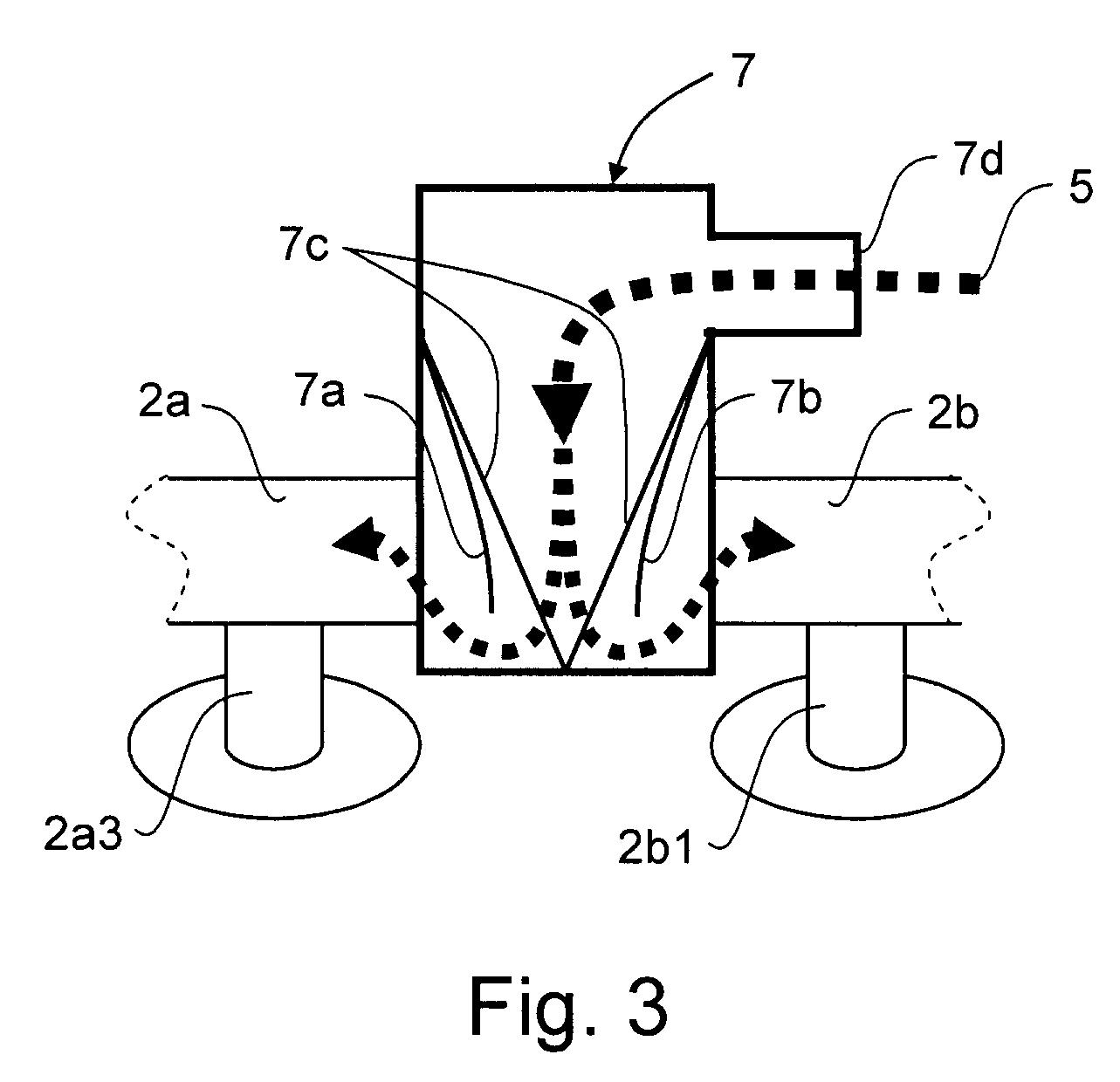
[0025]However, in order to reduce the cost and complexity of such a secondary air injection system 1 usually a common secondary air injection pump (not shown) is used, the air of which, illustrated by arrow 5, is then selectively fed via tubing 4 into the respective exhaust banks 2a, 2b using a resp...


PUM


Abstract

The present invention relates to a secondary air injection system for an internal combustion engine, and an automotive vehicle comprising such a secondary air injection system. The arrangement includes shut-off valve for selectively passing on or restricting airflow form the secondary air injection system. A flexible connector is arranged to receive the airflow and pass it on to at least two reed-type non-return valves arranged to substantially only allow airflow in the downstream direction. At the downstream side of each respective reed-type non-return valve a conduit for communicating any airflow passed there through to an associated exhaust bank of the internal combustion engine.

Description

FIELD OF INVENTION[0001]The present invention relates to an arrangement in a secondary air injection system for an internal combustion engine. Moreover, the present invention also concerns a secondary air injection system comprising such an arrangement and an automotive vehicle comprising such a secondary air injection system.BACKGROUND OF THE INVENTION[0002]In the field of motor vehicles which are operated by means of internal combustion engines it is a general requirement that the concentration of certain regulated substances, such as unburnt residues of hydrocarbons (HC), oxides of nitrogen (NOx) and carbon monoxide (CO), in the engine's exhaust gas should be as low as possible. In today's motor vehicles equipped with gasoline engines, a purification of the exhaust gas is normally carried out by means of a catalytic converter, or catalyst, arranged in the exhaust system. In the contemporary so-called three-way catalyst, the major part of the above-mentioned substances is eliminat...

Claims


Application Information

Patent Timeline
Patent Type & Authority Patents(United States)
IPC IPC(8): F01N3/00
CPCF01N3/22F01N3/227F01N3/30F01N3/34Y02T10/20Y02A50/20Y02T10/12
Inventor WASSMUR, ROBERTBLOMROOS, MAGNUS
Owner VOLVO CAR CORP
Why Eureka
Try Eureka