Method and arrangement for cooling an exhaust system

a technology for exhaust systems and cooling systems, applied in exhaust treatment, electrical control, mechanical equipment, etc., can solve the problems of evaporative emissions, gas vaporization, engine heat loss, etc., and achieve the effect of reducing evaporative emissions

Inactive Publication Date: 2007-07-19
WASSMUR ROBERT
View PDF6 Cites 9 Cited by
  • Summary
  • Abstract
  • Description
  • Claims
  • Application Information

AI Technical Summary

Benefits of technology

[0012]Detection of this so-called hot soak condition after heavy load operation of said engine as a requisite for injecting the cooling airflow will contribute in counteracting the negative effects norm

Problems solved by technology

In addition, evaporative emissions occur when, for example, on hot days gasoline heats up and evaporates from both the gasoline tank and wherever fuel may be present throughout the engine.
After the car is turned off, the engine still remains hot for a period of time, and gas vaporizes then, as well, even when the car is parked.
Furthermore, pressure may build in the fuel system.
If any of the fuel injectors drip, excess gas is likely to build up in the engine, making it hard to start.
Still further, components arranged at or close to the exhaust system of the engine may suffer negative effects due to overheating thereof during the conditions

Method used


Image

  • Method and arrangement for cooling an exhaust system
  • Method and arrangement for cooling an exhaust system
  • Method and arrangement for cooling an exhaust system

Examples


Embodiment Construction

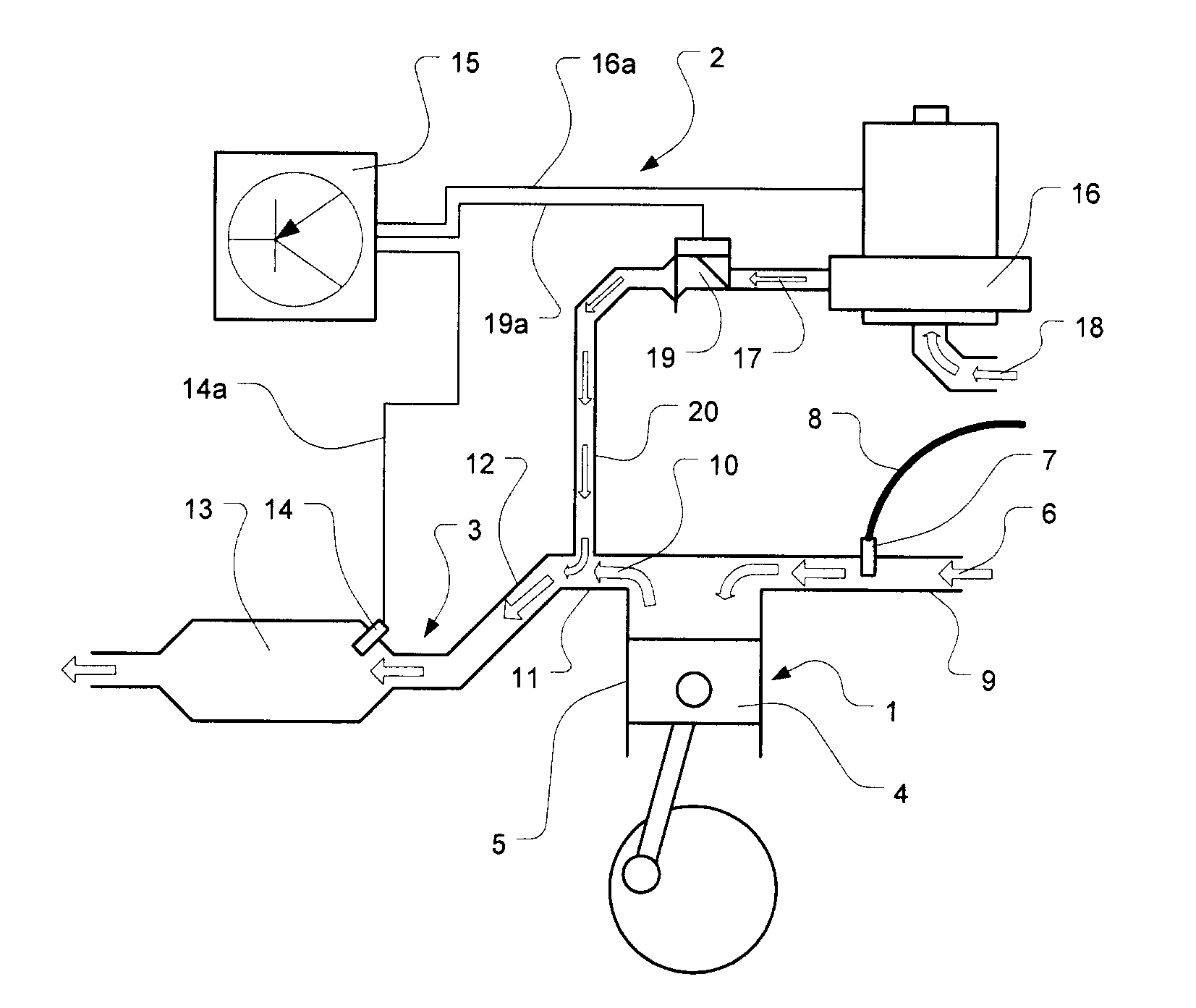
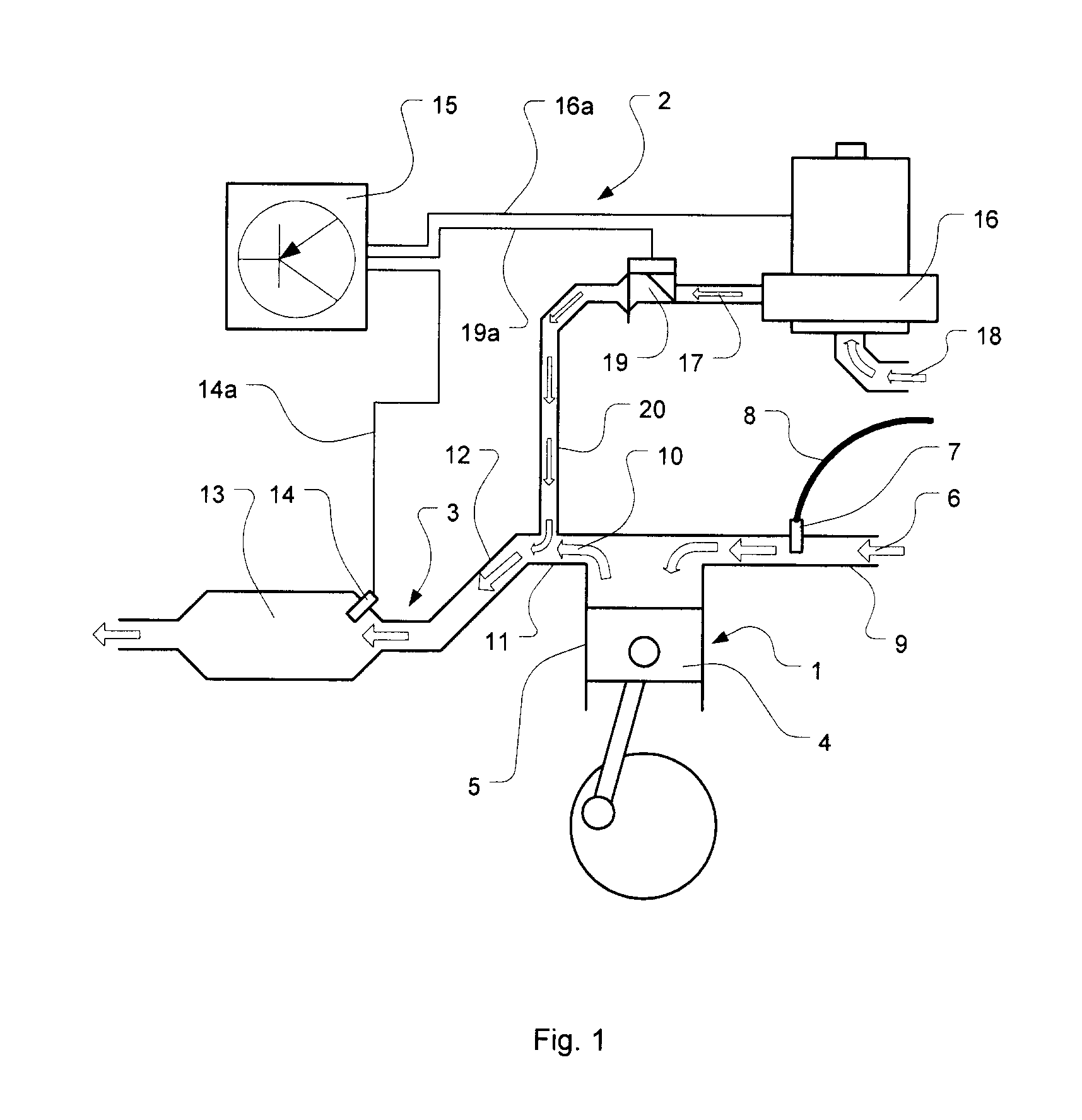
[0018]Referring to FIG. 1, there is illustrated schematically a simplified view of an internal combustion engine 1 having an arrangement 2 for cooling an associated exhaust system 3 in accordance with an embodiment of the present invention. A piston 4 is shown arranged within a cylinder 5 of the engine 1 in conventional manner. Fuel is injected into an air stream, illustrated by arrows 6, by means of a fuel injector 7 and its associated hosing 8. The fuel is injected into the air stream 6 inside an inlet manifold 9 of the engine 1 and mixes with the air stream 6, where after the air / fuel mixture in the inlet manifold 9 is introduced into the cylinder 5 by means of one or more inlet valves, not shown, in conventional manner. Following compression of the air / fuel mixture by the piston 4 the mixture is ignited to drive the piston 4 in conventional manner. Thereafter the produced exhaust gases, illustrated by arrows 10, are allowed to leave the cylinder by means of one or more exhaust v...


PUM


Abstract

The present invention relates to an arrangement for cooling an exhaust system of a vehicle having an internal combustion engine. The arrangement includes a controller for detecting an elevated temperature condition of the exhaust system, such as a so called hot soak condition, as well as detecting a predetermined engine operating status, such as either of an engine shutdown, a stopped or an idling status. A secondary air injection system may then be actuated to inject ambient air into the exhaust system thereby cooling said exhaust system.

Description

TECHNICAL FIELD[0001]The present invention relates to an arrangement for cooling an exhaust system of a vehicle having an internal combustion engine, and more particularly to a secondary air injection system comprising such an arrangement.BACKGROUND AND SUMMARY OF THE INVENTION[0002]In the field of motor vehicles which are operated by means of internal combustion engines it is a general requirement that the concentration of certain regulated substances in the engine's exhaust gas should be as low as possible. These substances are mainly present in the form of unburnt residues of hydrocarbons (HC), oxides of nitrogen (NOx) and carbon monoxide (CO). In today's motor vehicles equipped with gasoline engines, a purification of the exhaust gas is normally carried out by means of a catalytic converter, or catalyst, arranged in the exhaust system. In the contemporary so-called three-way catalyst, the major part of the above-mentioned substances is eliminated by means of various well-known c...

Claims


Application Information

Patent Timeline
IPC IPC(8): F01N3/00
CPCF01N3/2006F01N3/2046F01N3/22F01N3/32Y02T10/26F02D41/0235F02D41/1446F02D2041/0265F02D2200/0802F01N2260/022Y02A50/20Y02T10/12
Inventor WASSMUR, ROBERT
Owner WASSMUR ROBERT
Why Eureka
Try Eureka