
Collapsible cup assembly with a container lid

a container lid and collapsible technology, applied in the field of collapsible drinking cups with mountable lids, can solve the problems of difficult reassembling of the removed ring(s), difficult cleaning of edges and crevices, and sometimes accidentally separated rings

Inactive Publication Date: 2014-11-18
HUMANGEAR
View PDF37 Cites 49 Cited by
  • Summary
  • Abstract
  • Description
  • Claims
  • Application Information

AI Technical Summary

Benefits of technology

The patent describes a cup apparatus that can be expanded from a collapsed position to an expanded position for use. The apparatus includes a lid member that can be gripped and pulled apart to separate it from the cup. The lid member is attached to the cup and provides a stable platform for axially collapsing the cup around. The technical effect of the invention is to provide a convenient and flexible cup apparatus that can be easily expanded and collapsed for use.

Problems solved by technology

However, due to imperfections in the rings, or through wear over time, gaps can form between the rings leading to leakage.
Another deficiency of these traditional collapsible cups is that the rings can sometimes be accidentally separated through the pulling action to achieve the expanded form.
The separation requires the user to reassemble the removed ring(s) which can be difficult.
These edges and crevices can be difficult to clean and can harbor dirt and bacteria.
However, these elastomeric collapsible cups do not feature mountable lids or mountable lids with integrated containers.

Method used


Image

  • Collapsible cup assembly with a container lid
  • Collapsible cup assembly with a container lid
  • Collapsible cup assembly with a container lid

Examples


Embodiment Construction

[0041]While the present invention will be described with reference to a few specific embodiments, the description is illustrative of the invention and is not to be construed as limiting the invention. Various modifications to the present invention can be made to the preferred embodiments by those skilled in the art without departing from the true spirit and scope of the invention as defined by the appended claims. It will be noted here that for a better understanding, like components are designated by like reference numerals throughout the various figures.

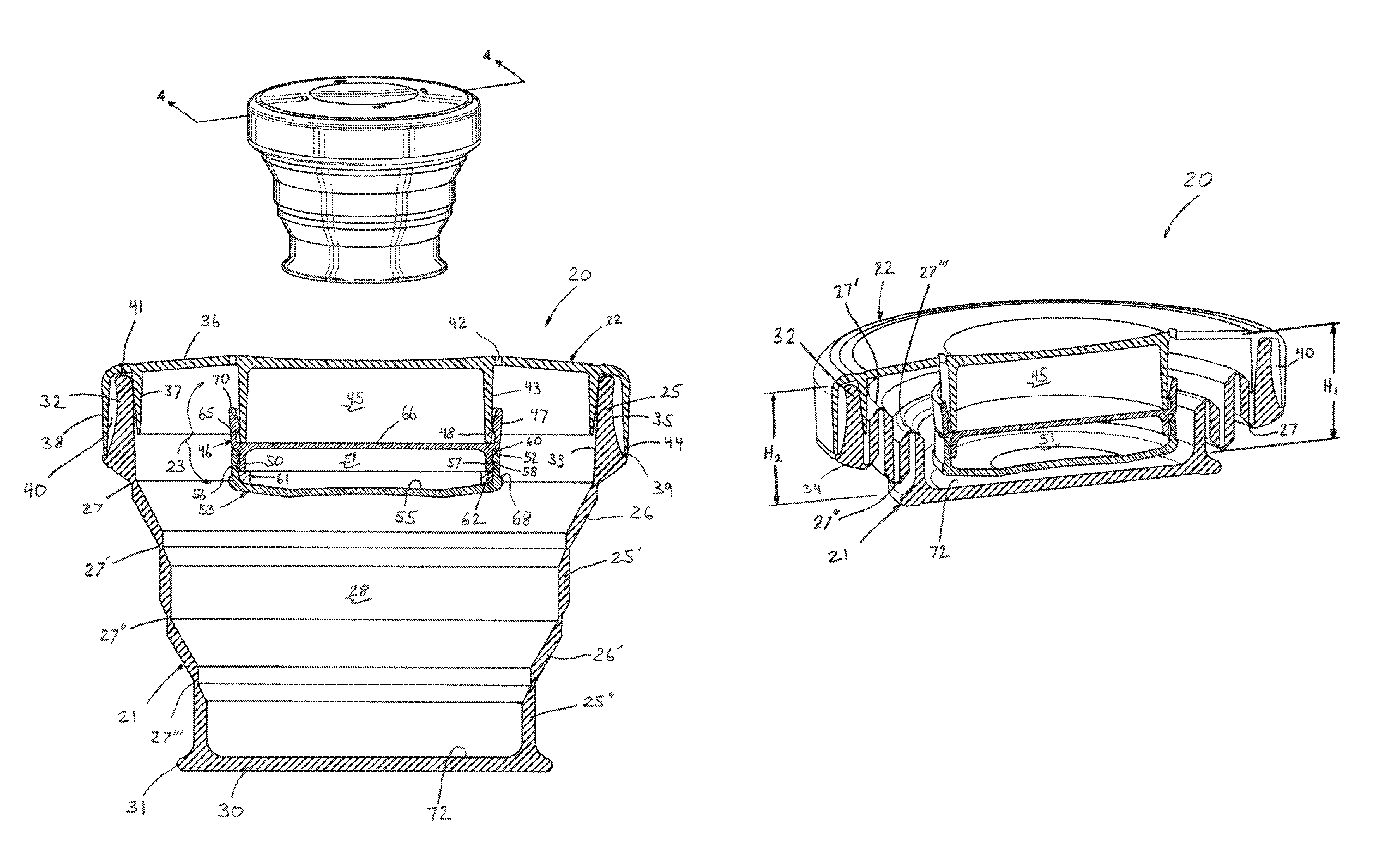
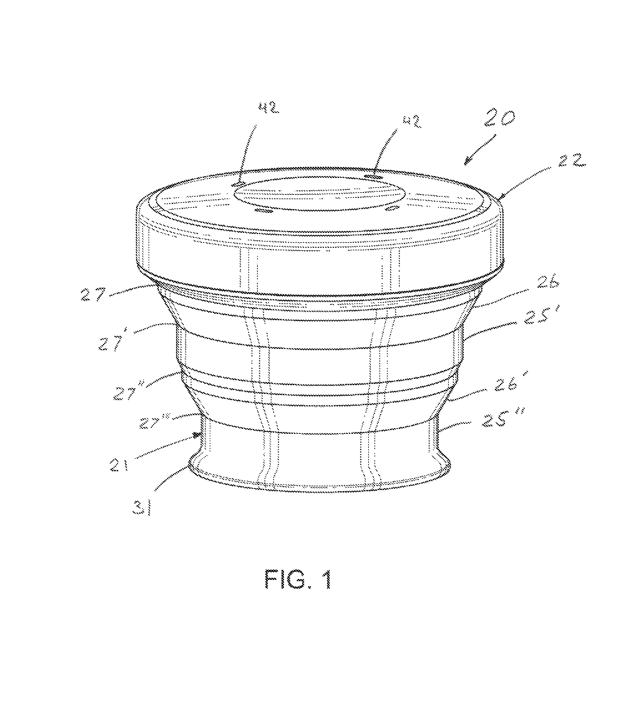
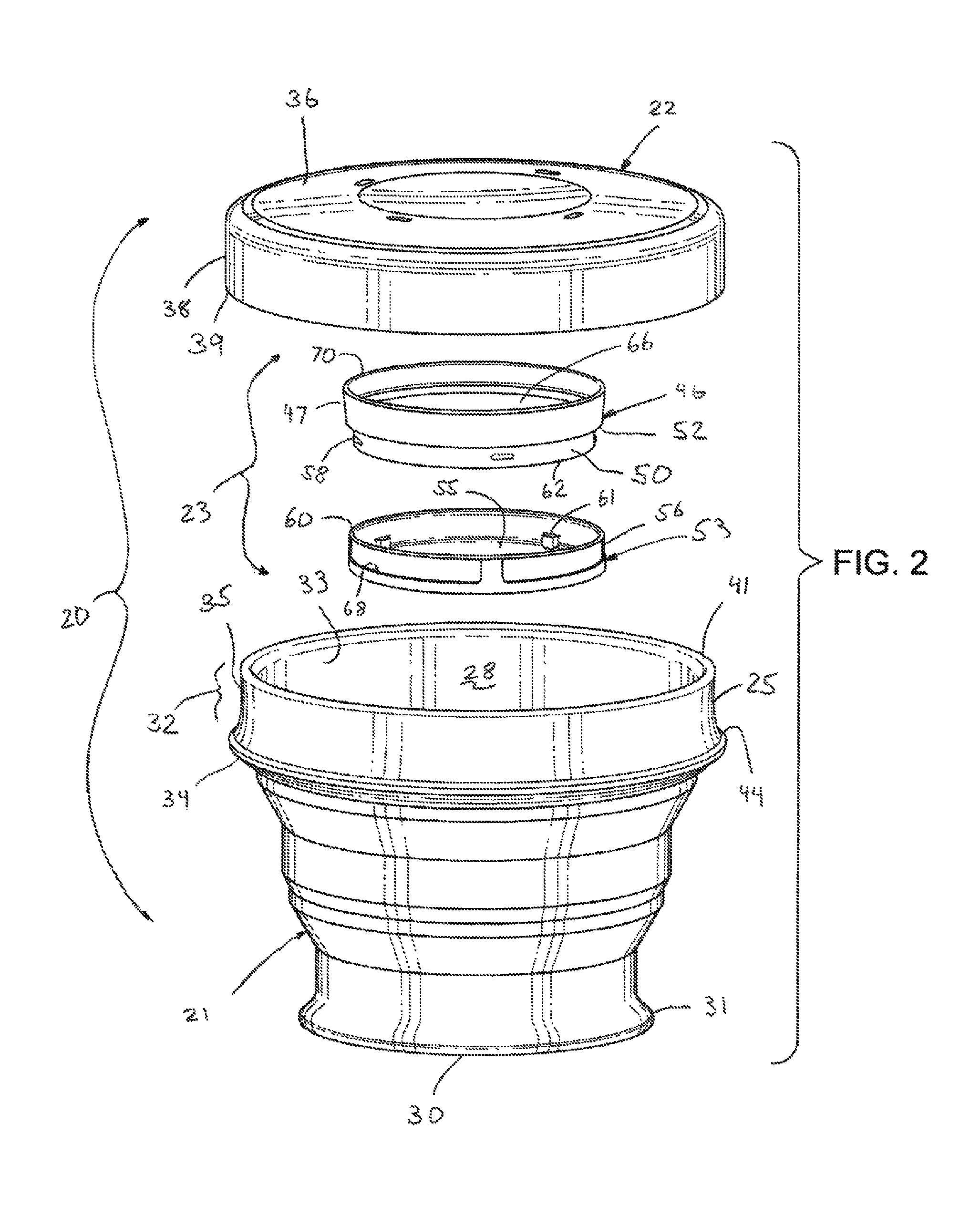
[0042]Turning now to FIGS. 1-5, a collapsible drinking cup assembly, generally designated 20, is provided having a flexible cup apparatus 21 with a mountable, relatively rigid lid or top lid member 22. In specific embodiments, the lid member 22 incorporates its own rigid container apparatus 23 integrated into the underside thereof. The cup apparatus 21 is manually movable between an operational expanded position (FIGS. 1-4 and 8) a...


PUM

PropertyMeasurementUnit
anglesaaaaaaaaaa
anglesaaaaaaaaaa
flexibleaaaaaaaaaa

Abstract

A collapsible drinking cup assembly having a plurality of annular ring segments each flexibly coupled together, end-to-end. An upper drinking lip segment of the ring segments includes an interior and exterior sidewall such that the drinking lip segment tapers inwardly from a lower base portion to an annular upper distal edge thereof. A support floor of the cup apparatus includes an annular bottom flange extending radially beyond an exterior wall of the bottom ring segment. Atop lid member extends over an opening into the cup apparatus, and includes a pair of opposed, inner and outer contact walls that collectively define an annular receiving groove therebetween. The cup apparatus can be expanded from a collapsed position to an expanded position when both the annular bottom flange and the lid member are radially gripped and axially pulled apart longitudinally thereof before separation of the lid member from the drinking lip segment.

Description

CROSS-REFERENCE TO RELATED APPLICATIONS[0001]This application claims priority under 35 U.S.C. §119(e) from U.S. Provisional Patent Application No. 61 / 587,835, filed Jan. 18, 2012, entitled “COLLAPSIBLE CUP ASSEMBLY WITH CONTAINER LID”, naming Miksovsky et al. as inventors, and which is incorporated herein by reference in its entirety and for all purposes.FIELD OF THE INVENTION[0002]The present invention relates to collapsible cups with mountable lids, and more particularly, with collapsible drinking cups with mountable lids having integrated container inventors, and which is incorporated herein by reference in its entirety and for all purposes.BACKGROUND OF THE INVENTION[0003]The present invention relates to collapsible cups with mountable lids, and more particularly, with collapsible drinking cups with mountable lids having integrated container.[0004]Current collapsible cups are typically made from concentric, tapered rings that nest into one another. These rings are generally made...

Claims


Application Information

Patent Timeline
Patent Type & Authority Patents(United States)
IPC IPC(8): B65D25/04A45F3/20B65D43/03B65D1/24B65D21/02A47G19/22B65D51/18B65D1/40
CPCY10S215/90B65D1/40A45F2003/205A45F3/20
Inventor MIKSOVSKY, CHRISTOPHER A.SLONE, CLINT N.
Owner HUMANGEAR
Learn More