Check patentability & draft patents in minutes with Patsnap Eureka AI!

Electrowetting display

a display device and display technology, applied in the field of electrowetting display devices, can solve the problems of low contrast of the display device obtained, decreased light extraction efficiency, and screen darkening, and achieve the effect of high-quality display without unevenness

Inactive Publication Date: 2014-11-25
SEKISUI CHEM CO LTD
View PDF8 Cites 6 Cited by
  • Summary
  • Abstract
  • Description
  • Claims
  • Application Information

AI Technical Summary

Benefits of technology

The invention allows for a display that shows bright and vivid colors with high contrast. It also results in a high-quality display that is free of unevenness.

Problems solved by technology

Therefore, light extraction efficiency decreases, and thus the screen becomes dark.
As a result, contrast of the display device that is obtained becomes low.
As described above, in the electrowetting device using the color filter, there is a problem in that bright and high-contrast color display may not be performed.
In addition, in the method, a relatively long time is taken, and thus there is a problem in that it is difficult to apply the method to a large-sized substrate.
However, in the method disclosed in Patent Document 2, there is a problem in that the hydrophobic liquid is partially agglomerates and thus unevenness occurs.

Method used


Image

  • Electrowetting display
  • Electrowetting display
  • Electrowetting display

Examples


first embodiment

[0049](First Embodiment)

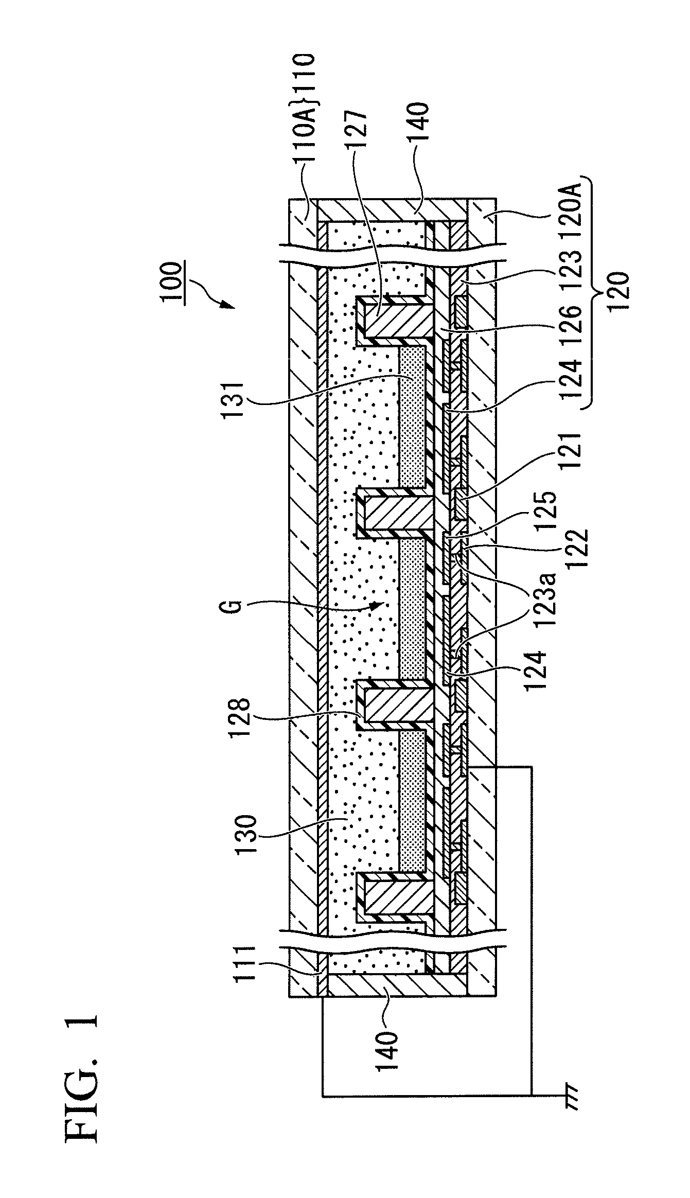
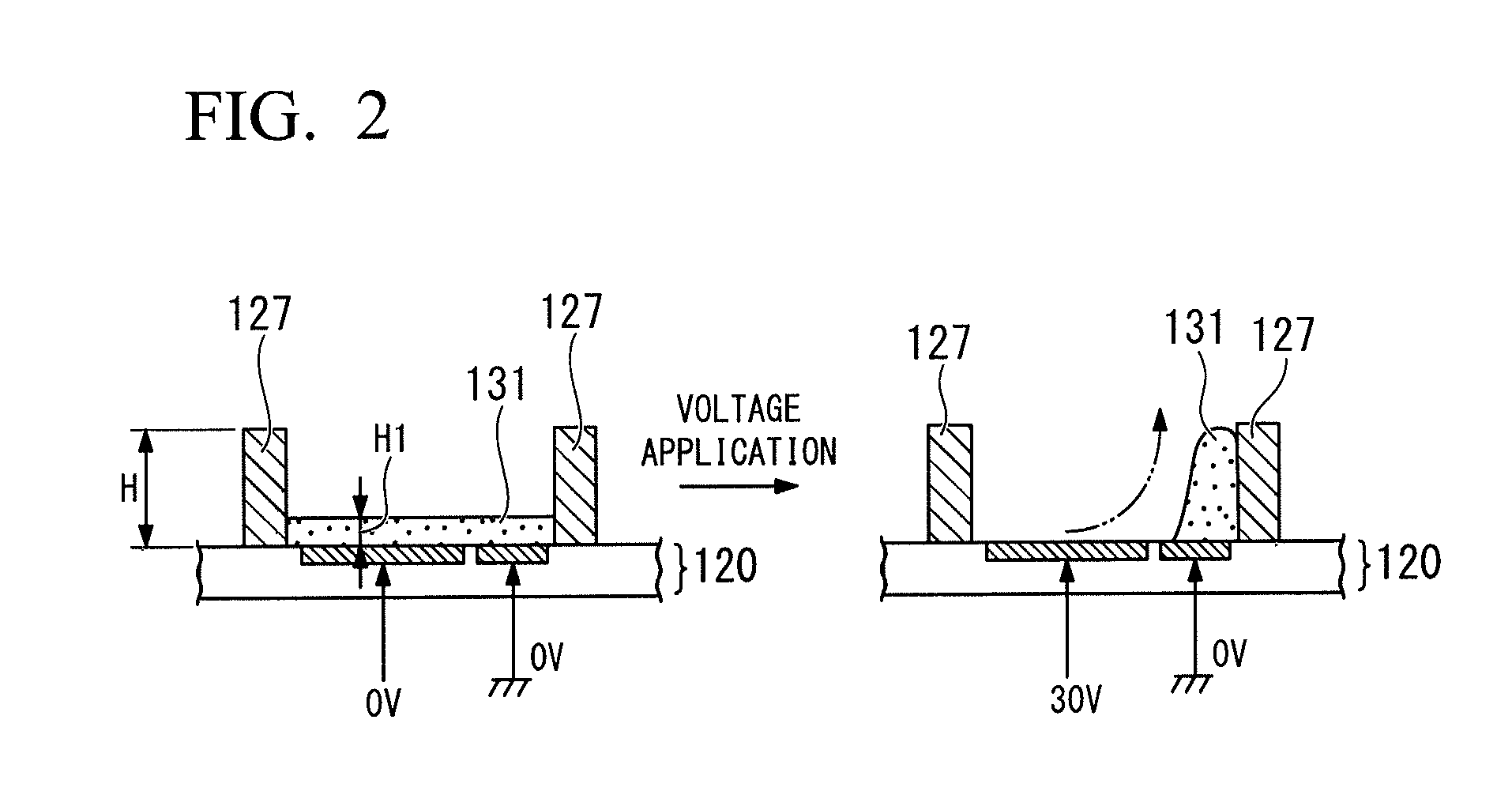
[0050]FIG. 1 shows a schematic diagram illustrating a cross-sectional configuration of an electrowetting display related to this embodiment, and FIG. 2 shows a diagram illustrating an operational concept of the electrowetting display. In addition, in FIG. 2, configuration of portions, which are not necessary for explanation, is simplified.

[0051]As shown in FIG. 1, an electrowetting display 100 includes a first substrate 110 and a second substrate 120, and these substrates 110 and 120 are disposed to be opposite to each other through a hydrophilic layer 130. The hydrophilic layer 130 is disposed at a region partitioned by a sealing member 140 that is provided along the outer periphery of the substrates 110 and 120.

[0052]The second substrate 120 includes a base material 120A, a TFT 121, a wiring portion 122, a planarization film 123, a pixel electrode 124, a common electrode 125, and an insulating film 126. The base material 120A is constituted by, for example,...

second embodiment

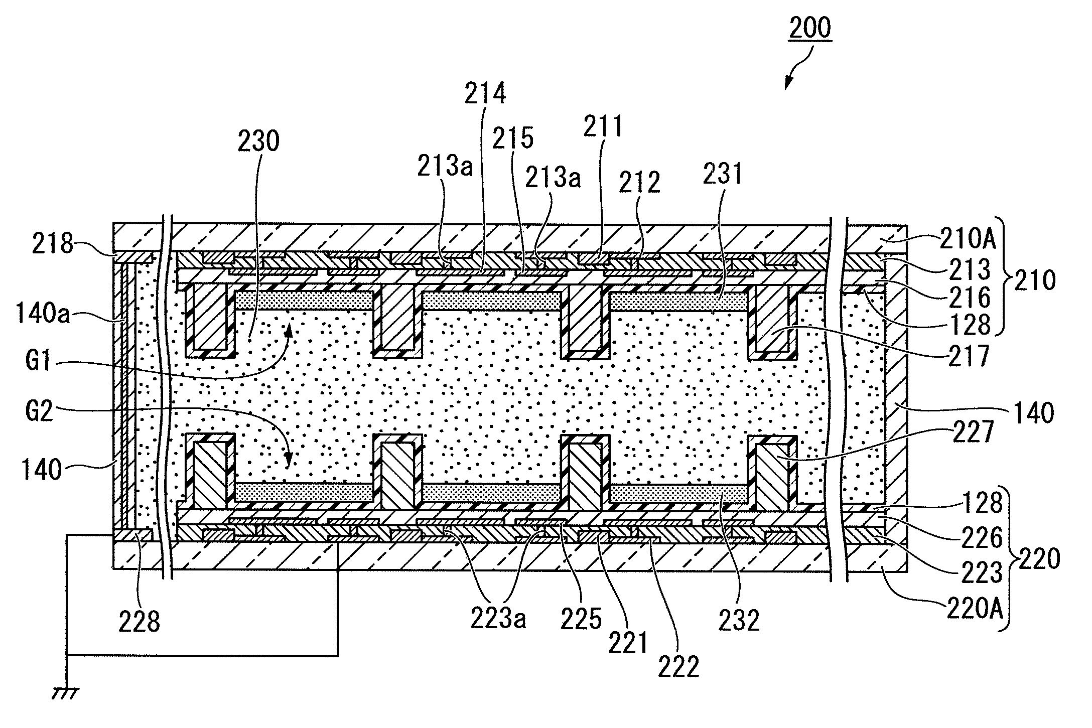
[0095](Second Embodiment)

[0096]The present inventors have found that in a case of introducing a drive system (hereinafter, may be referred to as an upper and lower drive system) in which a drive portion is provided to both of upper and lower substrates within a cell of an electrowetting device, when the electrowetting device is used as a display (display device), bright and high-contrast color display may be carried out. As a result, they have accomplished a configuration related to this embodiment. Hereinafter, a configuration related to a second embodiment of the electrowetting display will be described. Here, the same reference numerals will be given to the same members as the first embodiment, and detailed description thereof will be omitted or simplified.

[0097]FIG. 7 shows a diagram illustrating a cross-sectional configuration of the electrowetting display related to the second embodiment. FIGS. 8 and 9 show diagrams illustrating an operation of the electrowetting display, in w...


PUM


Abstract

Provided is an electrowetting device capable of performing bright and high-contrast color display. In addition, provided is an electrowetting device capable of performing high-quality display without unevenness.The electrowetting device is an electrowetting display in which each of a pair of substrate constituting one cell has a driving unit. A first substrate that stores a first hydrophobic liquid material in regions surrounded by a first pixel wall, and a second substrate that stores a second hydrophobic liquid material in regions surrounded by a second pixel wall are adhered to each other through a hydrophilic material.

Description

TECHNICAL FIELD[0001]The present invention relates to an electrowetting display.BACKGROUND ART[0002]Recently, an electrowetting device using an electrowetting effect has attracted attention. In general, in the electrowetting device, a hydrophilic (high surface-energy) liquid and a hydrophobic (low surface-energy) liquid are filled between a pair of substrates, and at least one of the substrates includes an electrode layer formed on a surface thereof, and a hydrophobic intermediate layer (insulating layer) that is formed on a surface of the electrode layer (for example, refer to Patent Document 1). The electrowetting device has the following characteristic. That is, when a voltage is applied between the hydrophilic liquid and the electrode layer through the hydrophobic intermediate layer, the hydrophilic liquid may be attracted to the hydrophobic intermediate layer, and thus an interface shape between the hydrophilic liquid and the hydrophobic liquid varies. The electrowetting device...

Claims


Application Information

Patent Timeline
Patent Type & Authority Patents(United States)
IPC IPC(8): G02B26/00G02B1/06G02B3/14G09F9/30G02B3/12G09F9/37
CPCG02B26/005G09F9/30G09F9/372G02B26/004G02B3/14
Inventor NAKASUGA, AKIRAUNATE, TAKAOWAKIYA, TAKESHINOMURA, SHIGEKI
Owner SEKISUI CHEM CO LTD
Features
  • R&D
  • Intellectual Property
  • Life Sciences
  • Materials
  • Tech Scout
  • Unparalleled Data Quality
  • Higher Quality Content
  • 60% Fewer Hallucinations
Learn More