Detecting malicious hardware by measuring radio frequency emissions

a radio frequency emission and hardware detection technology, applied in the direction of measurement devices, heterodyning/beat-frequency comparison, instruments, etc., can solve the problems of inability to detect the types of differences in electronic devices, the design of each component may be significant, and the authority to intentionally alter the electronic devi

Active Publication Date: 2014-12-02
LENOVO GLOBAL TECH INT LTD
View PDF11 Cites 220 Cited by
  • Summary
  • Abstract
  • Description
  • Claims
  • Application Information

AI Technical Summary

Problems solved by technology

A common printed circuit board may include tens or hundreds of individual components, and each component may have a design with significant complexity.
While some deviations may naturally or accidentally exist between two units of the same electronic device, it has also been found that some electronic devices may have been intentionally altered without authority.
These types of differences in the electronic device may not be easily detected through visual inspection or existing quality control techniques.

Method used


Image

  • Detecting malicious hardware by measuring radio frequency emissions
  • Detecting malicious hardware by measuring radio frequency emissions
  • Detecting malicious hardware by measuring radio frequency emissions

Examples


Embodiment Construction

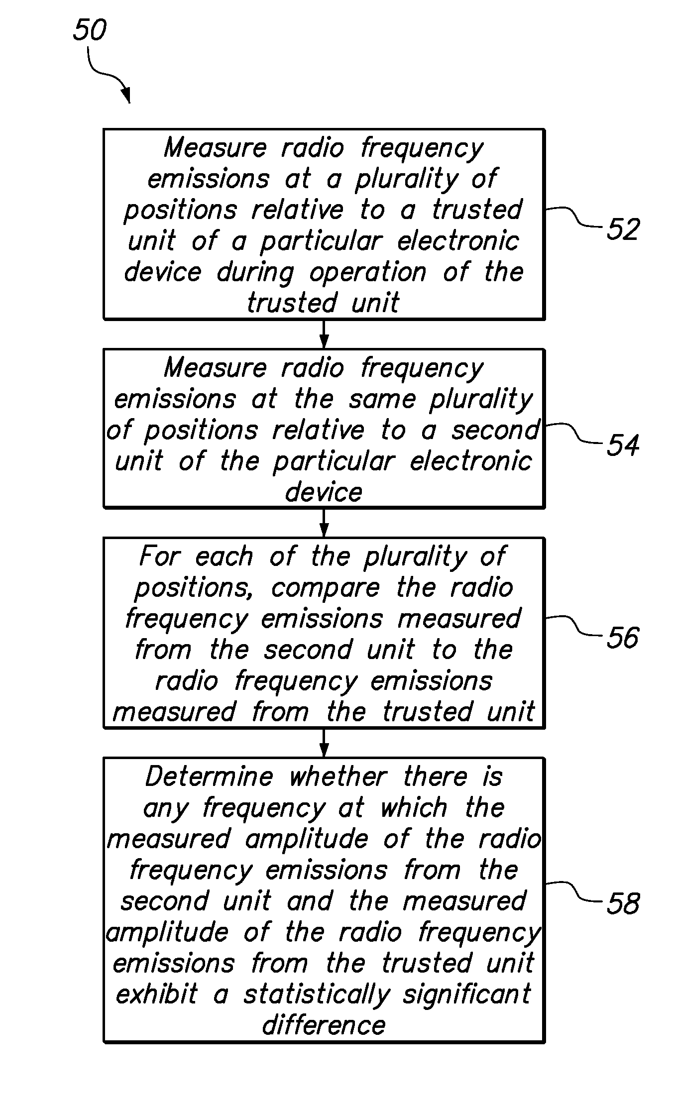
[0015]One embodiment of the present invention provides a method of testing an electronic device. The method comprises measuring radio frequency emissions at a plurality of positions relative to a trusted unit of a particular electronic device during operation of the trusted unit, and measuring radio frequency emissions at the same plurality of positions relative to a second unit of the particular electronic device. For each of the plurality of positions, the radio frequency emissions measured from the second unit are compared to the radio frequency emissions measured from the trusted unit. The method then determines whether there is any frequency at which the measured amplitude of the radio frequency emissions from the second unit and the measured amplitude of the radio frequency emissions from the trusted unit exhibit a statistically significant difference.

[0016]The trusted unit of the electronic device may, for example, be a prototype unit that was manufactured in a trusted enviro...


PUM


Abstract

A method of testing an electronic device includes measuring radio frequency emissions at a plurality of positions relative to a trusted unit of a particular electronicdevice during operation of the trusted unit, and measuring radio frequency emissions at the same plurality of positions relative to a second unit of the particular electronic device. For each of the plurality of positions, the radio frequency emissions measured from the second unit are compared to the radio frequency emissions measured from the trusted unit. The method then determines whether there is any frequency at which the measured amplitude of the radio frequency emissions from the second unit and the measured amplitude of the radio frequency emissions from the trusted unit exhibit a statistically significant difference.

Description

BACKGROUND OF THE INVENTION[0001]1. Field of the Invention[0002]The present invention relates to methods of testing electronic hardware.[0003]2. Background of the Related Art[0004]Electronic devices and systems may include any number of electronic components. A common printed circuit board may include tens or hundreds of individual components, and each component may have a design with significant complexity. Although great effort and care may go into designing an electronic device, the individual components may be designed and manufactured by many different companies, and the electronic device may be assembled under various degrees of supervision and security. As a result of the many potential variations that could exist in an electronic device made under a given product specification, it is recommended and often necessary to test some or all of the electronic devices received from an outside source before putting those electronic devices into service.[0005]While some deviations may...

Claims


Application Information

Patent Timeline
Patent Type & Authority Patents(United States)
IPC IPC(8): G01R23/14
CPCG01R29/0814
Inventor JONES, PHILLIP D.PAHEL, JR., THOMAS D.PARKER, ADAM J.RODRIGUEZ, ADRIAN X.
Owner LENOVO GLOBAL TECH INT LTD
Why Eureka
Try Eureka