Flanged material and standing seam clamp

a technology of flanged material and standing seam, which is applied in the direction of snow traps, mounting/supports of heat collectors, light and heating apparatus, etc., can solve the problems of ultimately affecting the integrity of the roof, so as to increase the surface tension

Active Publication Date: 2014-12-16
HEADER GREGORY A
View PDF30 Cites 60 Cited by
  • Summary
  • Abstract
  • Description
  • Claims
  • Application Information

AI Technical Summary

Problems solved by technology

Clamp assemblies that do not penetrate a standing seam are known; however, these devices use bolts that are tightened directly against the seam which can damage the seam and ultimately affect the integrity of the roof.
Prior art clamping assemblies also produce an uneven clamping pressure that is not evenly distributed against the seam eventually leading to clamp or roof failure.
Many other roofs clamps are known, but in each of these cases the device is complicated and difficult to install quickly.

Method used


Image

  • Flanged material and standing seam clamp
  • Flanged material and standing seam clamp
  • Flanged material and standing seam clamp

Examples


Embodiment Construction

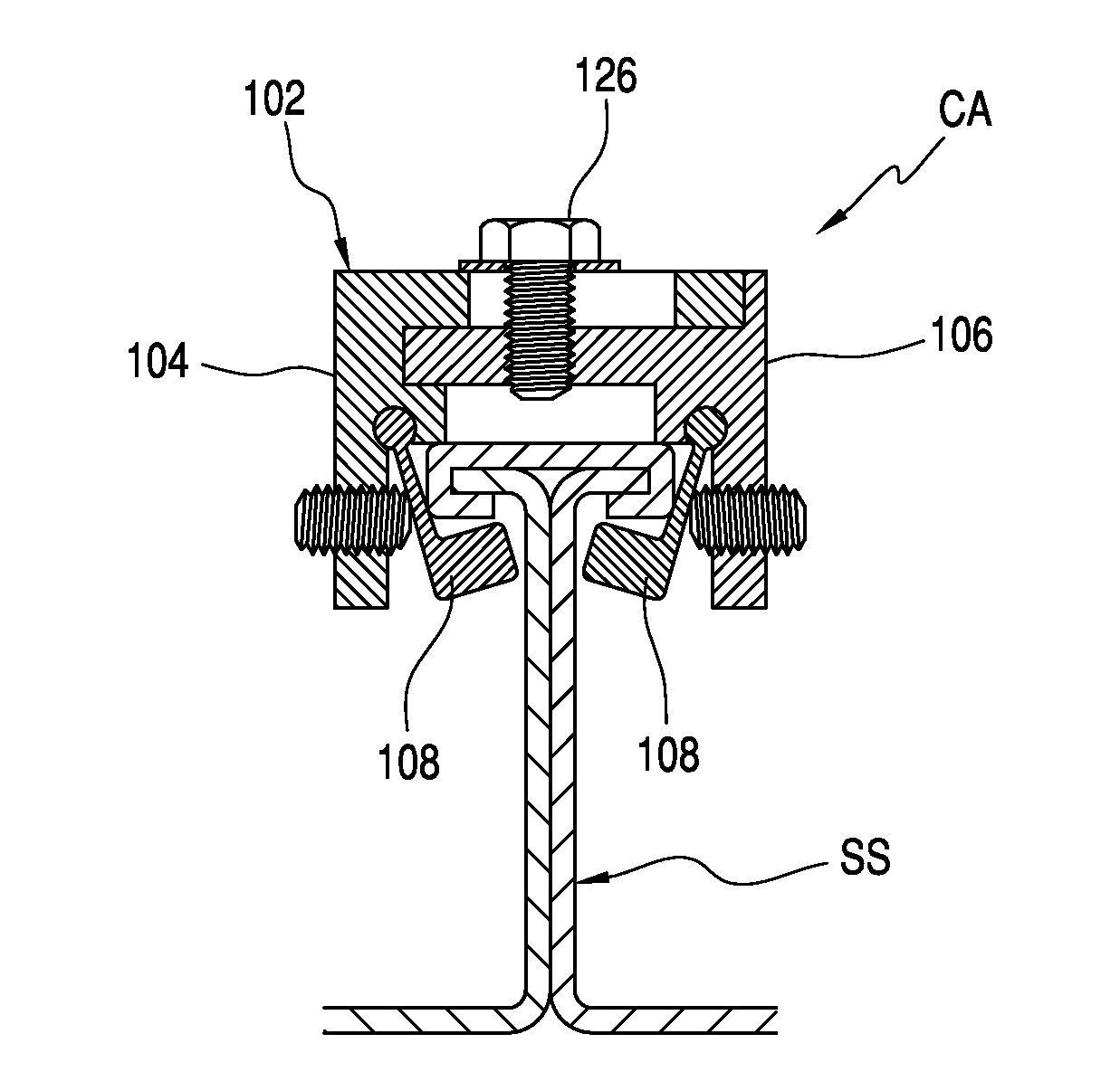
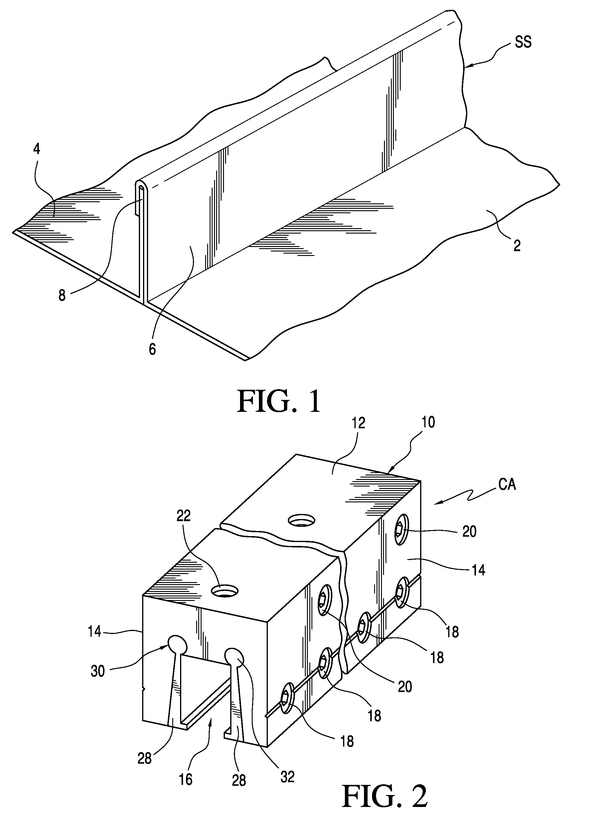
[0057]FIG. 1 shows a standard overlap-type standing seam SS comprising metal sheets 2 and 4 interconnected at upstanding portion 6 and head portion 8. The standing seam SS is formed by bending or profiling together adjacent edges of sheets 2 and 4 to interlock the edges at head portion 8 in a known manner. The present invention is applicable for clamping other standing seams as will be explained further below.

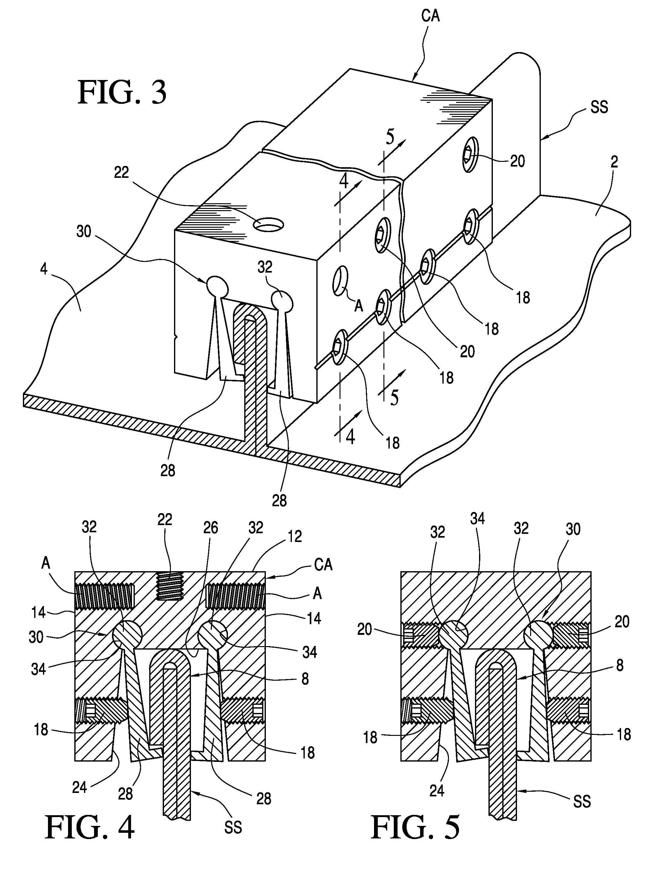
[0058]Referring to FIGS. 2 through 5, the clamp assembly CA of the present invention is shown in greater detail. As best seen in FIG. 2, the clamp assembly CA comprises a generally U-shaped clamp body 10, formed from metal such as extruded aluminum or a high density plastic or other material, and having a top 12 and sides 14 that define an interior region 16 for receiving a standing seam. The clamp body 10 may be of variable length and thickness depending upon the end use of the clamp and the strength requirements necessary for that particular use.

[0059]Adjustment screws 18 are...


PUM


Abstract

A clamping assembly for attaching loads to various kinds of flanged seams, the assembly comprising a generally U-shaped clamp body, at least one clamping hammer disposed interior of the clamp body, the clamping hammer is secured to the clamp body along the longitudinal axis of the clamp body, at least one adjustment screw extending through the clamp body and adapted to selectively impinge against the clamping hammer and cause it to pivot about its axis or otherwise move inwardly within the clamp body, the adjustment screw extending transverse to the longitudinal axis of the clamping hammer, at least one locking screw adapted to selectively impinge against the clamping hammer to prevent pivoting of the same may be optionally provided whereby a standing seam received within the clamp body may be tightly grasped between the clamp body and the clamping hammer under action of the adjustment screw.

Description

CROSS-REFERENCE TO RELATED APPLICATIONS[0001]This application is a continuation in part of International application No. PCT / US2012 / 039283, filed on May 24, 2012 and claiming priority on U.S. Ser. No. 13 / 118,308, filed on May 27, 2011, now U.S. Pat. No. 8,528,888 having an issue date of Sep. 10, 2013.FIELD OF THE INVENTION[0002]This invention is a clamp assembly for attaching loads to various kinds of flanged seams including, but not limited to, standing seam roofing.BACKGROUND OF THE INVENTION[0003]Standing seams are often used to interconnect metal panels to form the roof of a building or other structure. The seam is created by bending and profiling together adjacent side edges of two metal sheets to form an upwardly extending portion that interlocks the sheets as it extends the width or length of the roof surface. The head or uppermost portion of the seam may be formed in a variety of shapes depending upon the manner in which the sheets are profiled together. For example, the hea...

Claims


Application Information

Patent Timeline
Patent Type & Authority Patents(United States)
IPC IPC(8): B23Q3/02F16B2/06E04D13/10F24J2/52
CPCE04D13/10F24J2/5249F16B2/065Y02E10/47Y02B10/20Y10T403/7067F16B2/10F24S25/615
Inventor HEADER, GREGORY, A.
Owner HEADER GREGORY A
Why Eureka
Try Eureka