Constant force spring perimeter seal for an electromagnetic shielded door

a technology of electromagnetic shielding and constant force springs, applied in the direction of door/window fittings, warlike protection, stepping stones, etc., can solve the problems of requiring a large amount of force to engage and disengage, prone to wear, and requires excessive maintenan

Inactive Publication Date: 2015-01-06
RUST STEPHEN VINCENT
View PDF42 Cites 16 Cited by
  • Summary
  • Abstract
  • Description
  • Claims
  • Application Information

AI Technical Summary

Benefits of technology

[0006]In another aspect of the present invention, an electromagnetic shielded door with constant force spring perimeter seal comprises: a door panel, wherein the door panel comprises a sealing member having a raised sealing surface around a perimeter of an inside face of the door panel; and a door jamb having at least one spring containment member along a channel along an inside perimeter facing the raised sealing surface of the door panel, wherein a spring mechanism attaches to the channel.

Problems solved by technology

Existing radio frequency (RF) shielded doors utilize a mechanical contact mechanism that is prone to wear, requires excessive maintenance, and requires a large amount of force to engage and disengage.
Currently, RF door seal mechanisms encounter a large amount of mechanical resistance to opening and closing the door.
There have also been reports of injuries sustained to the wrist, shoulder, and back of operators using this style door.
The latching mechanism is also prone to failure which poses a possible safety concern of locking people inside of an RF shielded room.

Method used


Image

  • Constant force spring perimeter seal for an electromagnetic shielded door
  • Constant force spring perimeter seal for an electromagnetic shielded door
  • Constant force spring perimeter seal for an electromagnetic shielded door

Examples


Embodiment Construction

[0018]The following detailed description is of the best currently contemplated modes of carrying out exemplary embodiments of the invention. The description is not to be taken in a limiting sense, but is made merely for the purpose of illustrating the general principles of the invention, since the scope of the invention is best defined by the appended claims.

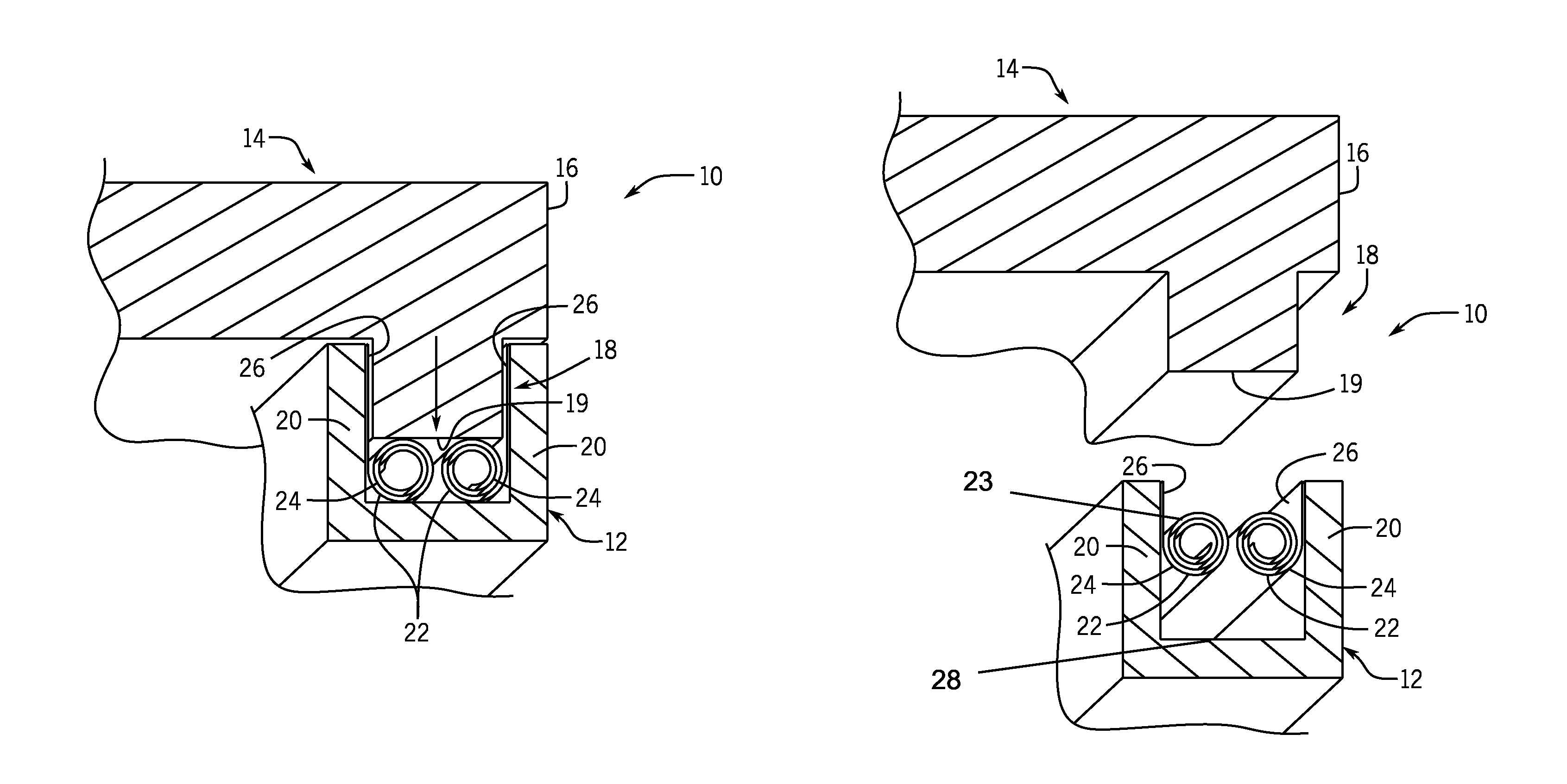
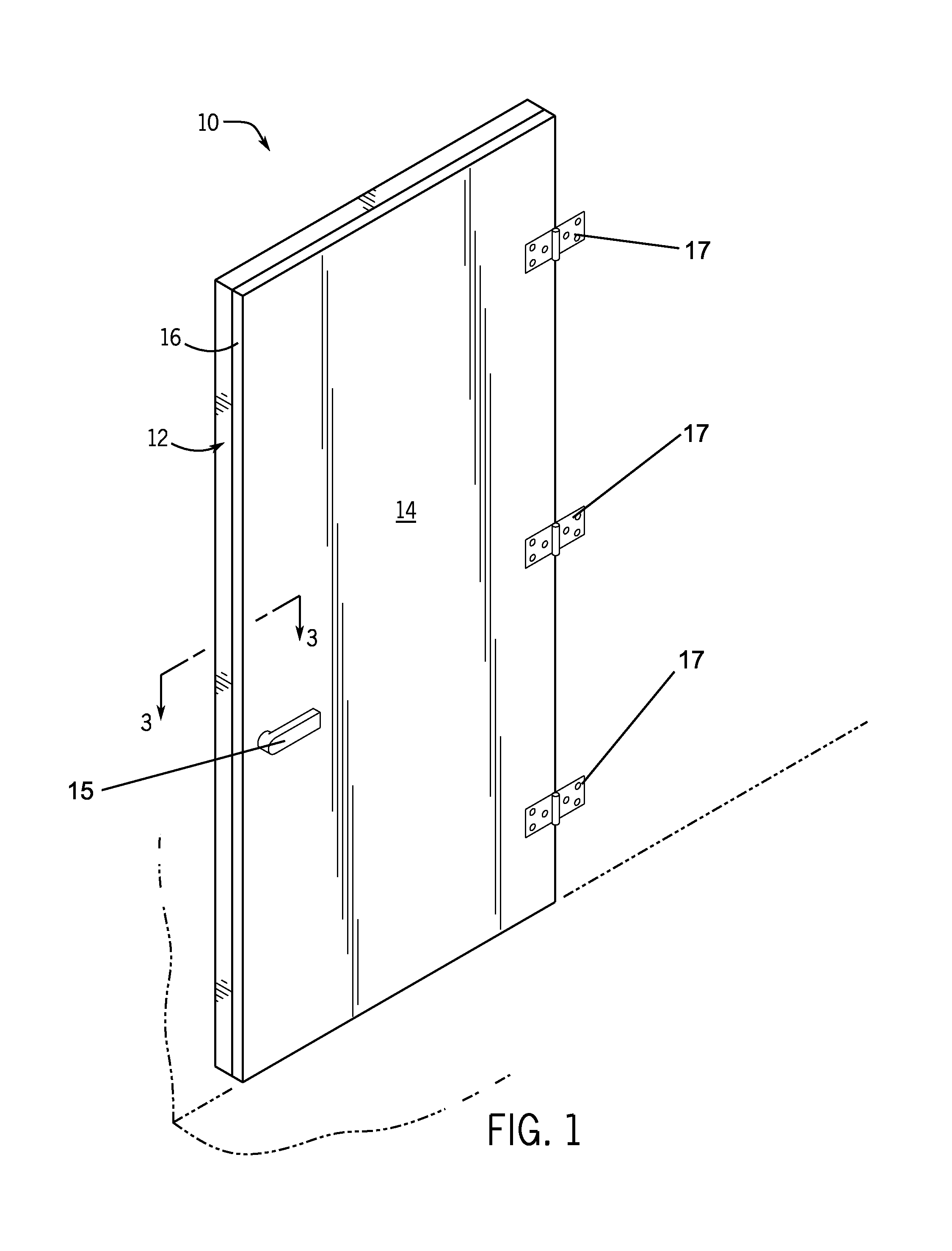
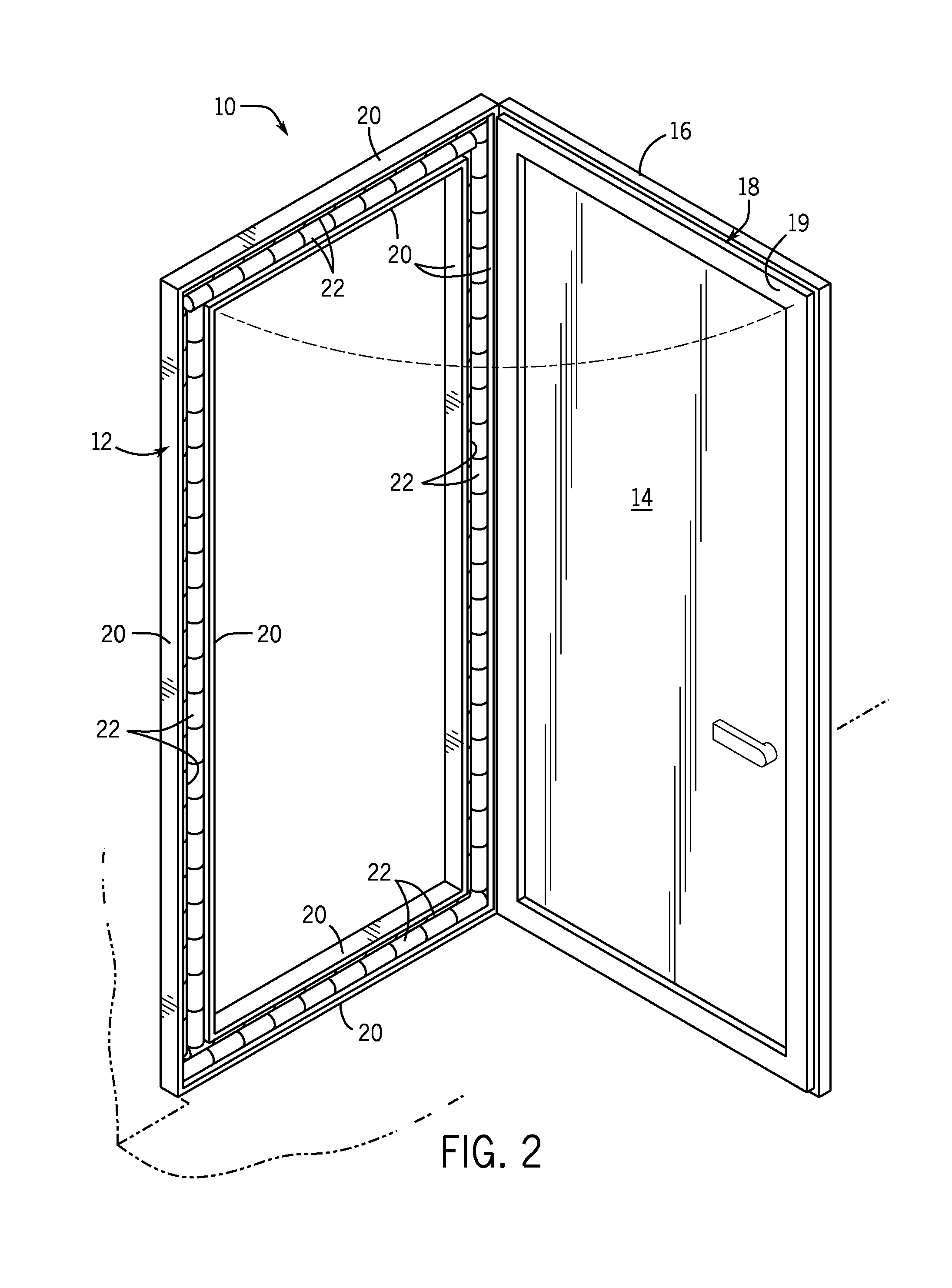
[0019]Broadly, an embodiment of the present invention provides an electromagnetic shielded door with constant force spring perimeter seal may include a door panel and door jamb. The door panel may include a sealing member around a perimeter of an inside face of the door panel. In certain embodiments, the sealing member may have a raised sealing surface. The door jamb may have at least one spring containment member along an inside perimeter facing the door panel. A spring mechanism may attach to the at least one spring containment member. The spring mechanism may include a plurality of continuous force flat torsion roller springs...


PUM


Abstract

An electromagnetic shielded door with constant force spring perimeter seal may include a door panel and door jamb. The door panel may include a sealing member around a perimeter of an inside face of the door panel. In certain embodiments, the sealing member may have a raised sealing surface. The door jamb may have at least one spring containment member along an inside perimeter facing the door panel. A spring mechanism may attach to the at least one spring containment member. The spring mechanism may include a plurality of continuous force flat torsion roller springs attached to at least one spring containment member which may be part of a channel. The raised sealing surface may engage with the plurality of continuous force flat torsion roller springs on the at least one spring containment member of the channel.

Description

BACKGROUND OF THE INVENTION[0001]The present invention relates to perimeter seals for electromagnetic shielded doors and, more particularly, to a constant force spring perimeter seal for an electromagnetic shielded door.[0002]Existing radio frequency (RF) shielded doors utilize a mechanical contact mechanism that is prone to wear, requires excessive maintenance, and requires a large amount of force to engage and disengage. Existing RF door seal mechanisms rely on a scraping action of a knife edge between two rows of compression spring.[0003]Currently, RF door seal mechanisms encounter a large amount of mechanical resistance to opening and closing the door. As a result, large mechanical handles, levers, cam mechanisms, and elaborate latching schemes are required to overcome this force. In addition, if no externally powered mechanism is present to aid in the opening of the door, the opening of the door relies entirely on the strength of an individual to overcome the compressive force ...

Claims


Application Information

Patent Timeline
Patent Type & Authority Patents(United States)
IPC IPC(8): H05K9/00E06B5/10E06B7/18
CPCE06B7/18E06B5/10E06B5/18E06B7/232
Inventor RUST, STEPHEN VINCENT
Owner RUST STEPHEN VINCENT
Why Eureka
Try Eureka