Real-time local and global SAR estimation for patient safety and improved scanning performance

a local and global sar estimation and scanning performance technology, applied in the field of diagnostic imaging arts, can solve the problems of limiting local sar, limiting the rf power, duty cycle and flip angle usable, and lengthening the scan acquisition time to meet designated sar limits, etc., to achieve optimal rf pulse sequence, increase the calculation speed of sar values, and efficient verification

Active Publication Date: 2015-01-27
KONINK PHILIPS ELECTRONICS NV
View PDF15 Cites 4 Cited by
  • Summary
  • Abstract
  • Description
  • Claims
  • Application Information

AI Technical Summary

Benefits of technology

[0011]One advantage is the ability to efficiently verify that a parallel transmission scan does not violate existing FDA or International Electrotechnical Commission limits.
[0012]Another advantage lies in increased calculation speed of SAR values, hotspots, and spatial SAR distribution.
[0013]Another advantage lies in the ability to customize the SAR calculation to individual patients.
[0014]Another advantage lies in the ability to create an optimal RF pulse sequence based on a patient's SAR profile.
[0015]Another advantage lies in the ability to determine specific information, such as E-fields and patient positions, on a patient-by-patient basis.

Problems solved by technology

For many MR applications at higher field strengths, the local SAR is a limiting factor.
The SAR deposition increases with higher field strength and limits the RF power, duty cycle, and flip angles usable, leading to a lengthening of scan acquisition time to meet designated SAR limits.
This is generally not sufficient for whole body imaging, as SAR hotspots can vary in both position and magnitude from patient to patient, and from RF pulse to RF pulse.
Moreover, RF sequences that accommodate a known static hotspot may inadvertently exacerbate unknown, patient specific hotspots at other locations.
This solution, however, would limit the allowed RF duty cycle so much that the MRI system would become seriously compromised for use in conjunction with in vivo parallel transmission scans.
Use of bio-mesh models for E-field simulations instead of the actual patient leads to a systematic error that is difficult to characterize.
This process would take several minutes and cannot practically be carried out in real time as the patient waits inside the scanner for the actual diagnostic scan to begin.

Method used


Image

  • Real-time local and global SAR estimation for patient safety and improved scanning performance
  • Real-time local and global SAR estimation for patient safety and improved scanning performance
  • Real-time local and global SAR estimation for patient safety and improved scanning performance

Examples


Embodiment Construction

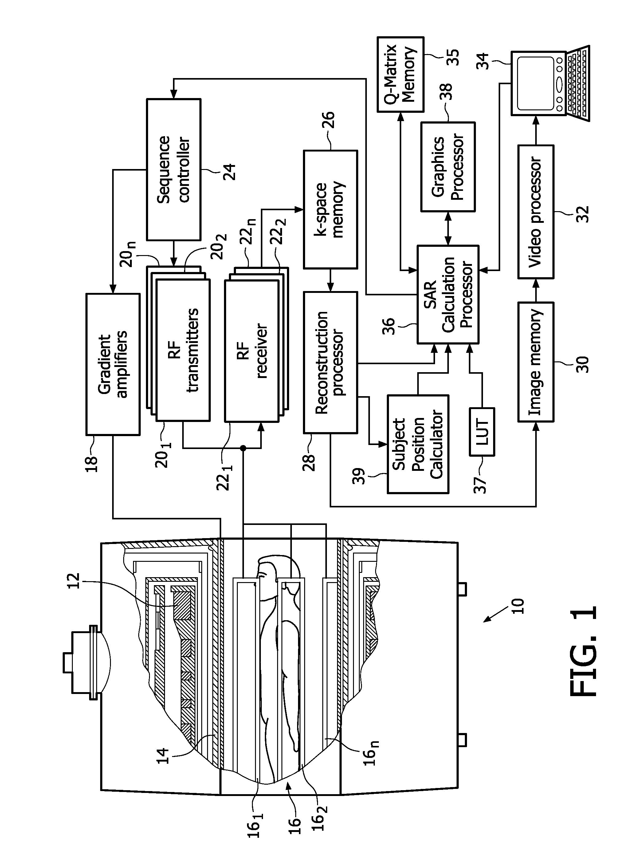
[0024]With reference to FIG. 1, a magnetic resonance scanner 10 is illustrated as a closed bore system that includes a solenoidal main magnet assembly 12, although open and other magnet configurations are also contemplated. The main magnet assembly 12 produces a substantially constant main magnetic field B0 oriented along a horizontal axis of an imaging region. It is to be understood that other magnet arrangements, such as vertical, and other configurations are also contemplated. The main magnet 12 in a bore type system may typically have a field strength of around 0.5 T to 7.0 T or more.

[0025]A gradient coil assembly 14 produces magnetic field gradients in the imaging region for spatially encoding the main magnetic field. Preferably, the magnetic field gradient coil assembly 14 includes coil segments configured to produce magnetic field gradient pulses in three orthogonal directions, typically longitudinal or z, transverse or x, and vertical or y directions.

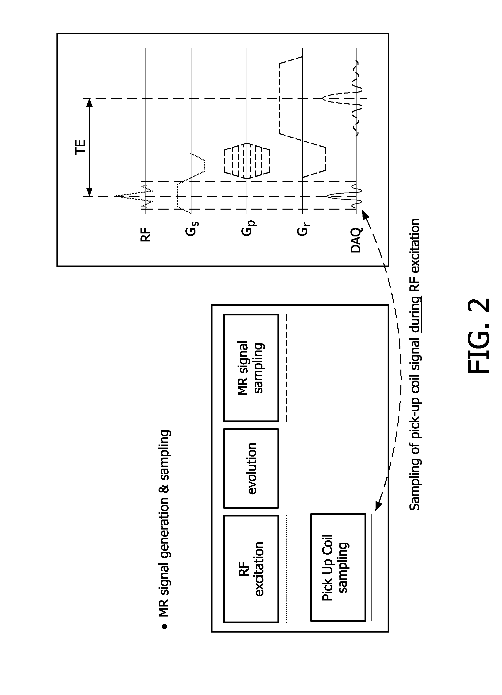
[0026]A radio frequency ...


PUM


Abstract

In a method and apparatus to enable increased RF duty cycle in high field MR scans, a specific energy absorption rate (SAR) calculation processor calculates the local and global SAR or even a spatial SAR map. By incorporating additional information as, e.g. patient position, the SAR calculation accuracy can be increased as well as by using more patient specific pre-calculated information (e.g. based on different bio meshes), the so called Q-matrices. A sequence controller maybe provided to create a global SAR optimal RF pulse. After the optimal RF pulse is applied, the SAR and its spatial distribution are determined. SAR hotspots are also determined. Q-matrices within an appropriate radius around the hotspots are averaged and added to a global Q-matrix in a weighted fashion. After the global Q-matrix is updated, a new optimal RF pulse is created.

Description

FIELD OF THE INVENTION[0001]The present application relates to the diagnostic imaging arts. It finds particular application in the context of patient safety and associated improved scanning performance (in terms of radio frequency (RF) duty cycle) and will be described with particular reference thereto. Furthermore, the estimation and suppression of local specific energy absorption rate (SAR) hot spots in connection with high field magnetic resonance imaging (MRI). It is to be appreciated, however, that it is also applicable to optimization and processing of other information, and is not necessarily limited to the aforementioned applications.BACKGROUND OF THE INVENTION[0002]For many MR applications at higher field strengths, the local SAR is a limiting factor. The SAR deposition increases with higher field strength and limits the RF power, duty cycle, and flip angles usable, leading to a lengthening of scan acquisition time to meet designated SAR limits. For a single transmitter sys...

Claims


Application Information

Patent Timeline
Patent Type & Authority Patents(United States)
IPC IPC(8): G01R33/44G01R33/28G01R33/561G01R33/565G01R33/58
CPCG01R33/583G01R33/5612G01R33/288G01R33/5659
Inventor GRAESSLIN, INGMARBIEDERER, SVENKATSCHER, ULRICHSCHWESER, FERDINANDBOERNERT, PETERHARVEY, PAUL ROYSTONMENS, WILHELMUS REINERIUS MARIA
Owner KONINK PHILIPS ELECTRONICS NV
Why Eureka
Try Eureka