
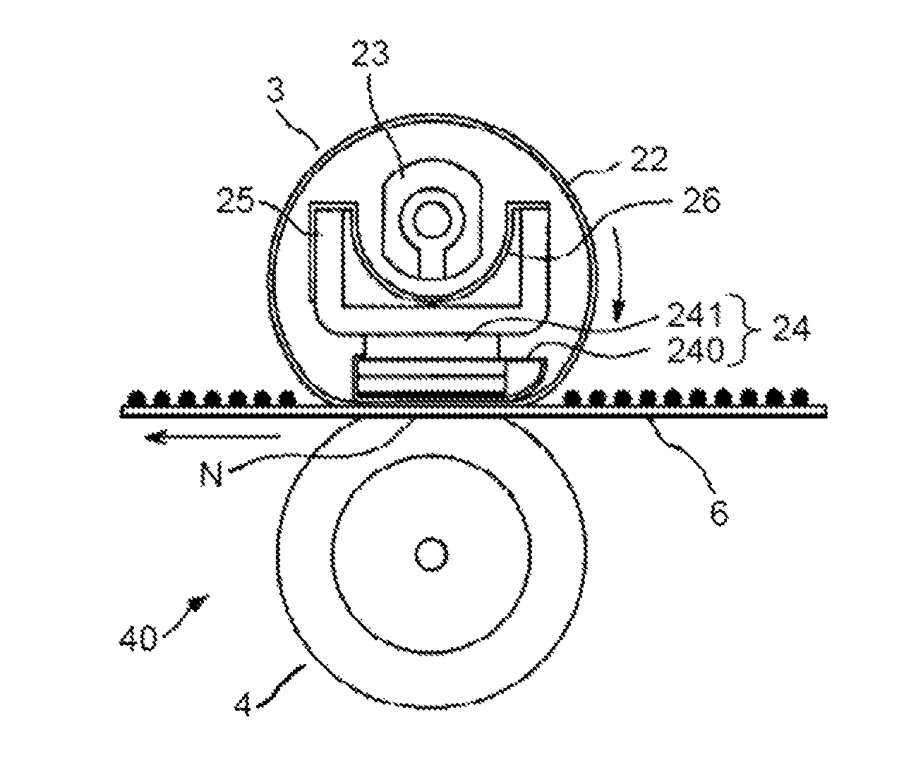
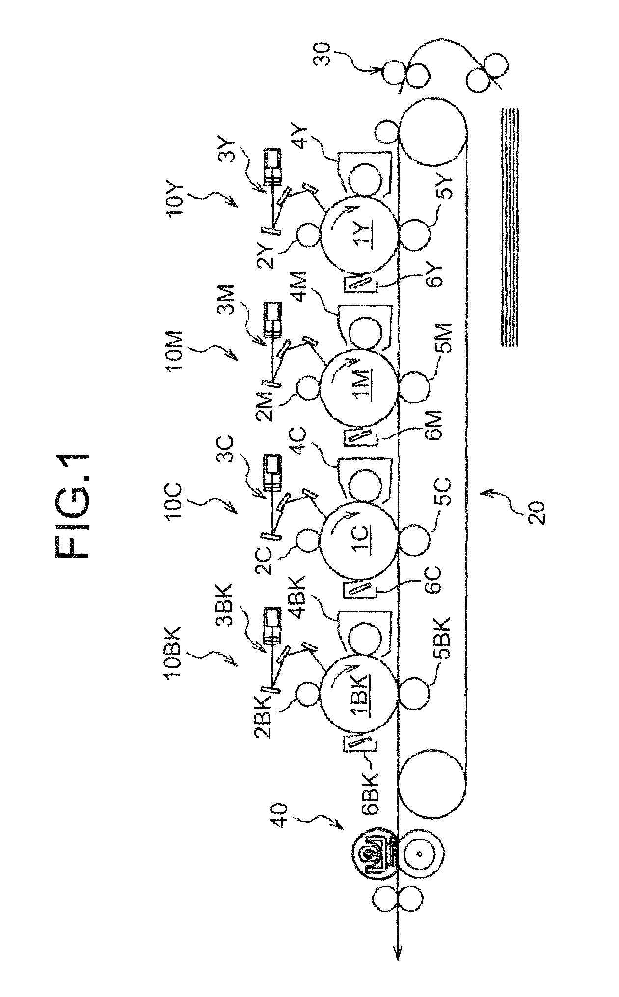
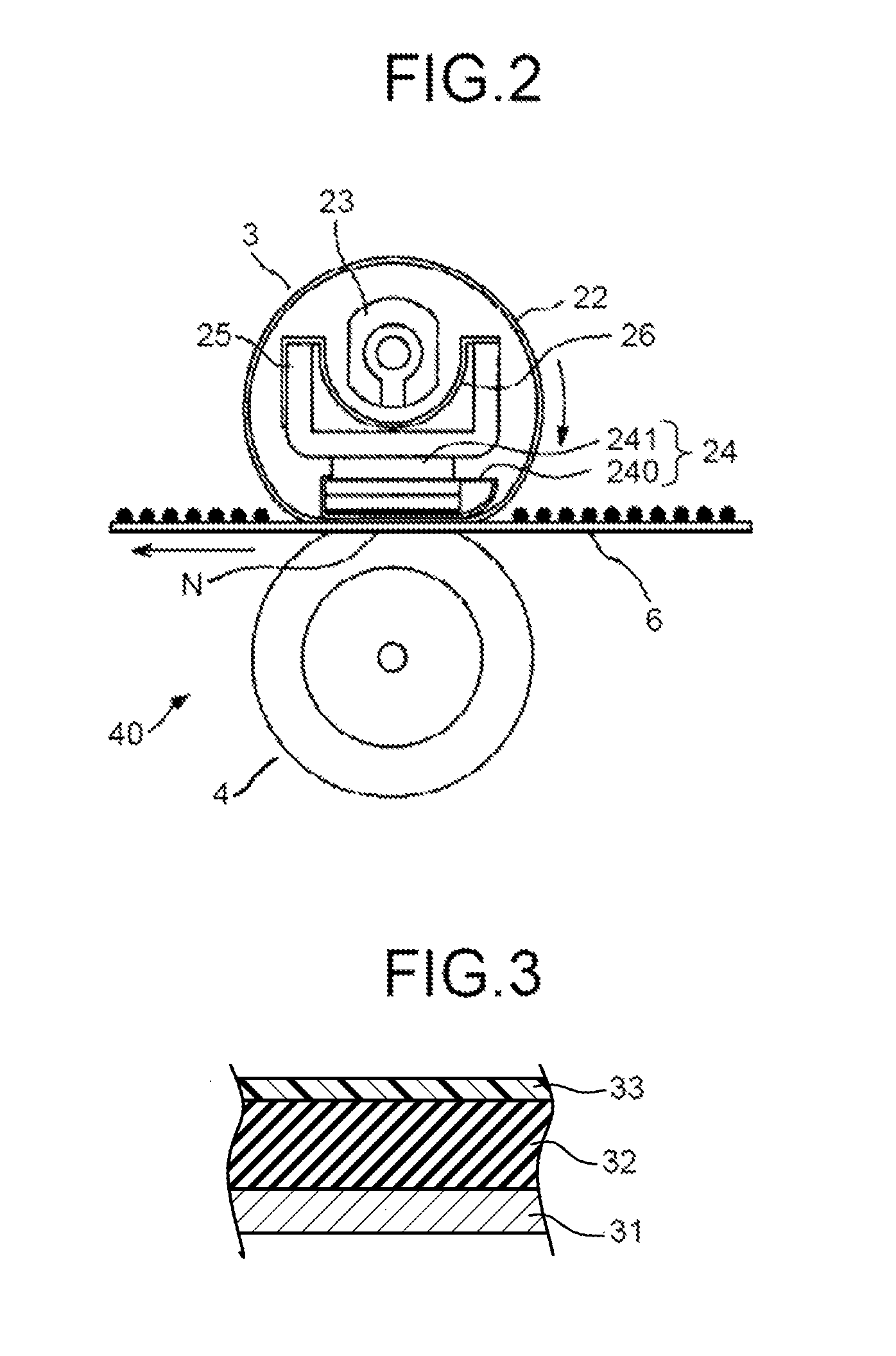
Fixing-unit roller, fixing unit, and image forming apparatus including an elastic layer

a technology of fixing unit and fixing unit, which is applied in the direction of electrographic process apparatus, instruments, optics, etc., can solve the problems of difficult to maintain a predetermined nip pressure, low endurance of sponge layer, sharp decrease of hardness of sponge layer,

Active Publication Date: 2015-02-03
RICOH KK
View PDF30 Cites 0 Cited by
  • Summary
  • Abstract
  • Description
  • Claims
  • Application Information

AI Technical Summary

Benefits of technology

The solution enables a wide nip width with a small diameter, reduces warm-up time, and enhances durability, ensuring high endurance and effective image fixation while maintaining compactness.

Problems solved by technology

However, although this technique can reduce warm-up time, the technique is disadvantageous in that the sponge layer has low endurance because an external force applied to the sponge layer damages the sponge layer in a short period.
Furthermore, hardness of the sponge layer decreases sharply, a nip pressure drops in a short period, making it difficult to maintain a predetermined nip pressure.
This results in insufficient image fixation.
As a result, a usable range of the roller becomes disadvantageously narrow.

Method used


Image

  • Fixing-unit roller, fixing unit, and image forming apparatus including an elastic layer
  • Fixing-unit roller, fixing unit, and image forming apparatus including an elastic layer
  • Fixing-unit roller, fixing unit, and image forming apparatus including an elastic layer

Examples


examples

[0066]The core bar formed from SUM material that was 18 mm in diameter was used. The elastic layer of silicone foam, having open cells, 3.5 mm in thickness and 342 mm in axial length, made from a water-foamed silicone composition manufactured by Toray Dow Corning Silicone Co., Ltd. was formed at a center portion on the outer peripheral surface of the core bar. Hardness of the elastic layer was ASKER-C 40 Hs.

[0067]A sheet-passing area at a center portion of this elastic layer was covered with a 30-μm-thick PFA tube as the releasing layer. A 50-μm-thick grip layer of silicone rubber was formed on each of portions near the opposite ends of the elastic layer where the releasing layer was not formed.

[0068]Three rollers were made from the water-foamed silicone composition described above in each of several different agitation conditions.

[0069]For each of the different agitation conditions, a porous material of the elastic layer of one of the three rollers was cut, and the obtained cross s...


PUM


Abstract

A fixing-unit roller includes: a core bar; and an elastic layer formed on an outer peripheral surface of the core bar. The elastic layer is formed from a porous material that contains a plurality of cells. Cells in a cross section obtained by cutting across the porous material are 0.1 μm or greater and 50 μm or less in size. A ratio of an area occupied by composite cells, which are made of partially-overlapping spherical cells, in a 200-μm square in the cross section to an area of the square is 60% or greater and 70% or less.

Description

CROSS-REFERENCE TO RELATED APPLICATIONS[0001]The present application claims priority to and incorporates by reference the entire contents of Japanese Patent Application No. 2012-026257 filed in Japan on Feb. 9, 2012.BACKGROUND OF THE INVENTION[0002]1. Field of the Invention[0003]The present invention relates to a fixing-unit roller such as a pressing roller used in a fixing unit in an electrophotographic copier, a printer, a facsimile, or the like to fix a not-yet-fixed toner image, and a fixing unit and an image forming apparatus including the fixing-unit roller.[0004]2. Description of the Related Art[0005]As fixing units used in various image forming apparatuses such as copiers, printers, facsimiles, and multifunction peripherals having functions of these machines, there have been known fixing units that include a thin fixing belt made up of a metal substrate and an elastic rubber layer, for example. Employing a thin fixing belt that is reduced in thermal capacity leads to conside...

Claims


Application Information

Patent Timeline
Patent Type & Authority Patents(United States)
IPC IPC(8): G03G15/20
CPCG03G15/206G03G15/2053G03G2215/2035
Inventor SUTO, KATSUNORIAZE, NORIHIKOENDOH, TAKESHIKAMI, MASAYUKIKOBAYASHI, TORUSHIODERA, KOHTA
Owner RICOH KK
Learn More