
Systems and methods for active optimized spatio-temporal sampling

a spatio-temporal sampling and active optimization technology, applied in the field of ultrasonic imaging, can solve problems such as user confusion

Active Publication Date: 2015-02-17
FUJIFILM SONOSITE
View PDF39 Cites 0 Cited by
  • Summary
  • Abstract
  • Description
  • Claims
  • Application Information

AI Technical Summary

Benefits of technology

[0007]The present invention is directed to systems and methods which provide active optimized spatio-temporal sampling (AOSTS) for image generation. Optimized spatio-temporal sampling (OSTS) is accomplished according to embodiments by selecting multi-beam sampling parameters, such as selecting the order of steered and straight rays fired within a frame, to provide optimized sampling in association with a portion of an imaged volume. For example, optimized spatio-temporal sampling may be accomplished by changing the multi-beam firing sequence so that a portion of an imaged volume is sampled in subsequent rays or beams (as opposed to subsequent frames) to thereby provide a location of minimal temporal sampling difference at the portion of the imaged volume.
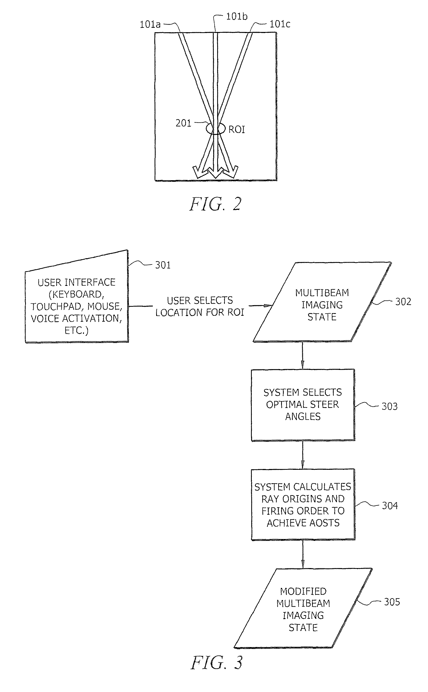
[0008]Embodiments of the invention actively select one or more regions of interest (ROIs) in a multi-beam ultrasound sampling mode, to minimize temporal image artifacts in the ROIs caused by image generation techniques such as spatial compounding process for example, and thereby provide AOSTS. Such selection of ROIs according to embodiments results in various multi-beam sampling parameters, such as the number of rays that are used, the spacing between the rays that are used, the width of the rays that are used, the sequence of the rays that are used, the angle of the rays that are used, etc., being selected to provide OSTS with respect to the selected ROIs. Embodiments of the invention may additionally or alternatively provide for various multi-beam sampling parameters being directly selected, such as to manually configure an OSTS operation, to adapt an OSTS operation for a particular attribute, etc. and thereby provide AOSTS.
[0012]AOSTS of embodiments of the present invention provides for OSTS being implemented with respect to strategic portions of a generated image. Accordingly, rather than applying OSTS with respect to a default location within a sampled volume, such as the middle of the image as would be the case with simple mixing of the order of steered and straight rays fired within a frame, selected portions of an imaged volume are provided the benefits of OSTS using AOSTS techniques of the present invention. Moreover, embodiments of the present invention provide AOSTS to achieve optimized sampling based on application specific needs.

Problems solved by technology

One drawback of the compounding methods now employed is that they result in temporal artifacts being introduced into the final image which, in turn, causes ambiguity to the user.

Method used


Image

  • Systems and methods for active optimized spatio-temporal sampling
  • Systems and methods for active optimized spatio-temporal sampling
  • Systems and methods for active optimized spatio-temporal sampling

Examples


Embodiment Construction

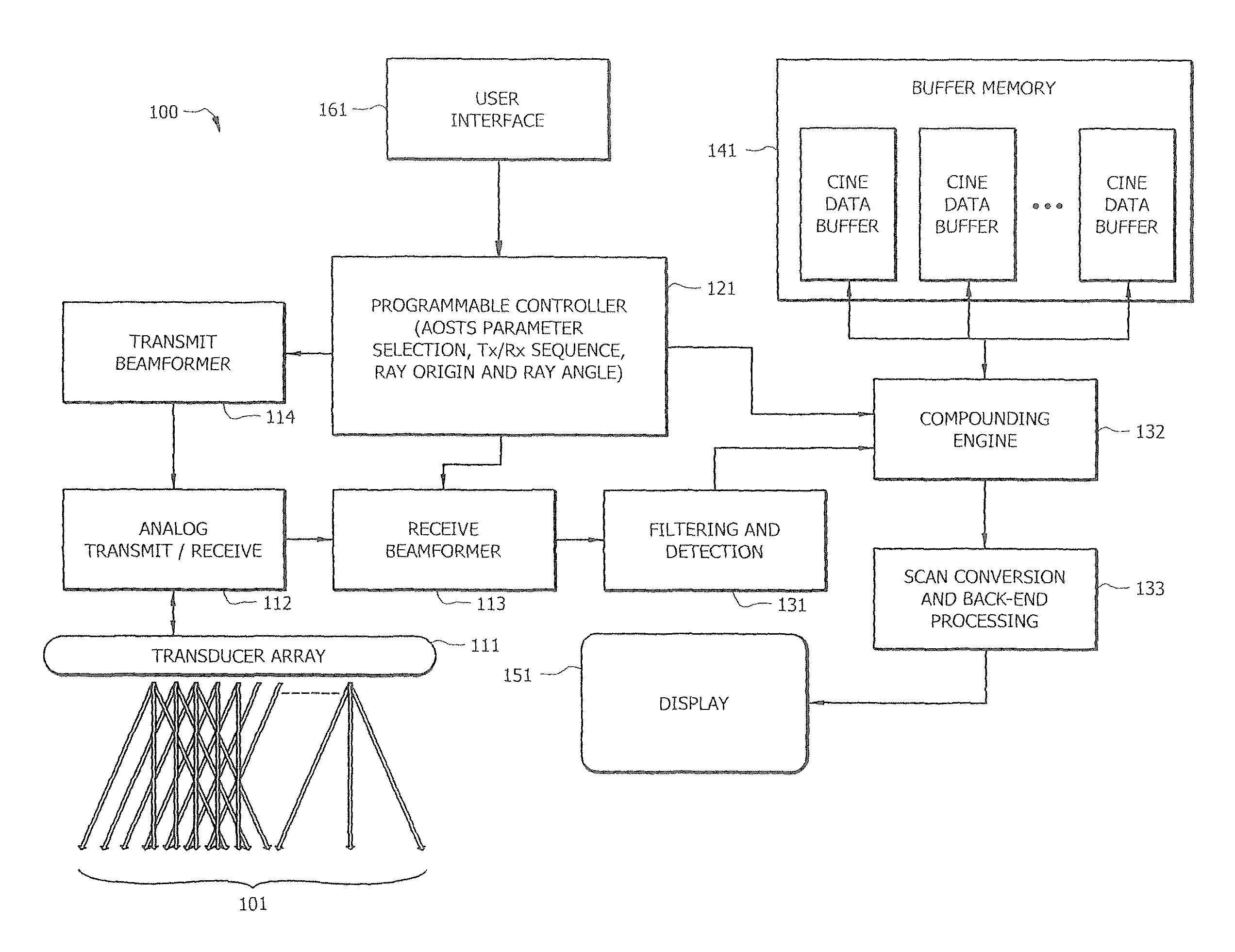
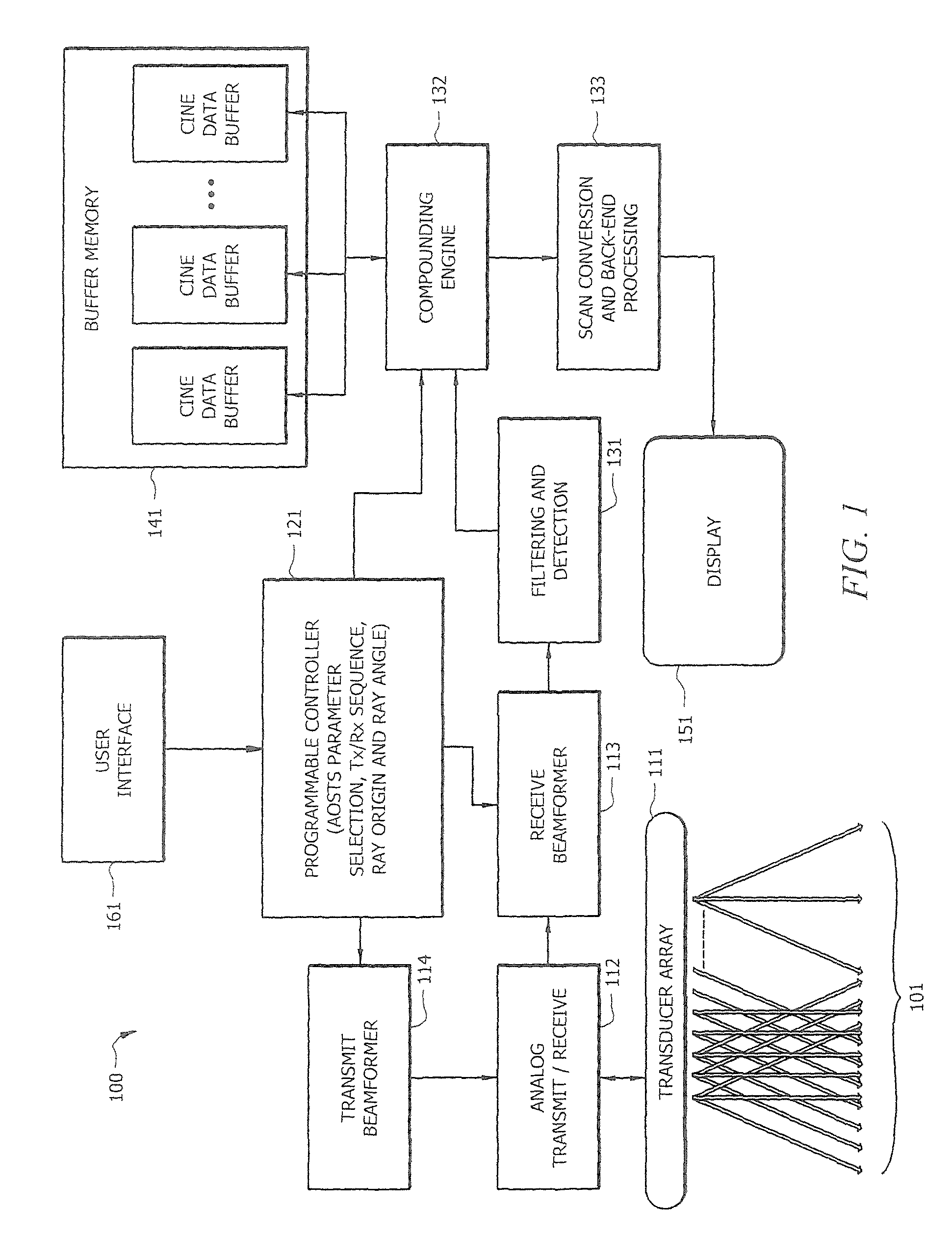
[0019]Directing attention to FIG. 1, system 100 adapted to provide AOSTS image processing according to embodiments of the invention is shown. To aid in understanding the concepts of the present invention, system 100 will be described herein with reference to an ultrasound imaging system, such as may comprise a diagnostic ultrasound system utilized with respect to medical examinations and / or performing medical procedures. However, it should be appreciated that concepts of the present invention are applicable to other imaging modalities, such as computer aided tomography (CAT), magnetic resonance imaging (MRI), X-ray imaging, etc.

[0020]In operation, controller 121 controls transmission and reception of sampling signals for imaging operations. In the illustrated embodiment, controller 121 operates with transmit beamformer 114, transmit / receive circuitry 112, and transducer array 111 to generate one or more of rays 101 for signal transmission and transducer array 111, transmit / receive c...


PUM


Abstract

Systems and methods which provide active optimized spatio-temporal sampling (AOSTS) for image generation are shown. Embodiments actively select one or more regions of interest (ROIs) in a multi-beam ultrasound sampling mode, to minimize temporal image artifacts in the ROIs and thereby provide AOSTS. Such selection of ROIs according to embodiments results in various multi-beam sampling parameters, such as the number of rays that are used, the spacing between the rays that are used, the width of the rays that are used, the sequence of the rays that are used, the angle of the rays that are used, etc., being selected to provide optimized spatio-temporal sampling with respect to the selected ROIs. Selection of ROIs according to embodiments may include selecting parameters such as position, size, shape, orientation, direction, rate of change, etc.

Description

CROSS-REFERENCE TO RELATED APPLICATIONS[0001]The present application is related to U.S. patent application Ser. No. 11 / 749,319 entitled “System and Method for Optimized Spatio-Temporal Sampling,” filed May 16, 2007, Ser. No. 12 / 269,663 entitled “Systems and Methods to Identify Interventional Instruments,” filed Nov. 12, 2008, and to U.S. provisional patent application Ser. No. 60 / 886,877 entitled “System and Method for Temporal Coherence Spatial Sampling,” filed Jan. 26, 2007, the disclosures of which are hereby incorporated by reference.TECHNICAL FIELD[0002]The invention relates to ultrasound imaging and more specifically to providing active optimized spatio-temporal sampling.BACKGROUND OF THE INVENTION[0003]Spatial compounding is a method of creating an ultrasound image by compiling multiple views or angles. Each view is obtained from multiple lines of sight at different angles. This is a departure from traditional ultrasound imaging that used a single line of sight. The views fro...

Claims


Application Information

Patent Timeline
Patent Type & Authority Patents(United States)
IPC IPC(8): A61B8/00G01S7/52G01S15/89
CPCA61B8/00A61B8/469G01S7/52085G01S15/8995G01S7/52063G01S7/52077
Inventor LUNDBERG, ANDREW K.HWANG, JUIN-JET
Owner FUJIFILM SONOSITE
Learn More