

System and method for optimized spatio-temporal sampling
- Summary
- Abstract
- Description
- Claims
- Application Information
AI Technical Summary
Benefits of technology
Problems solved by technology
Method used
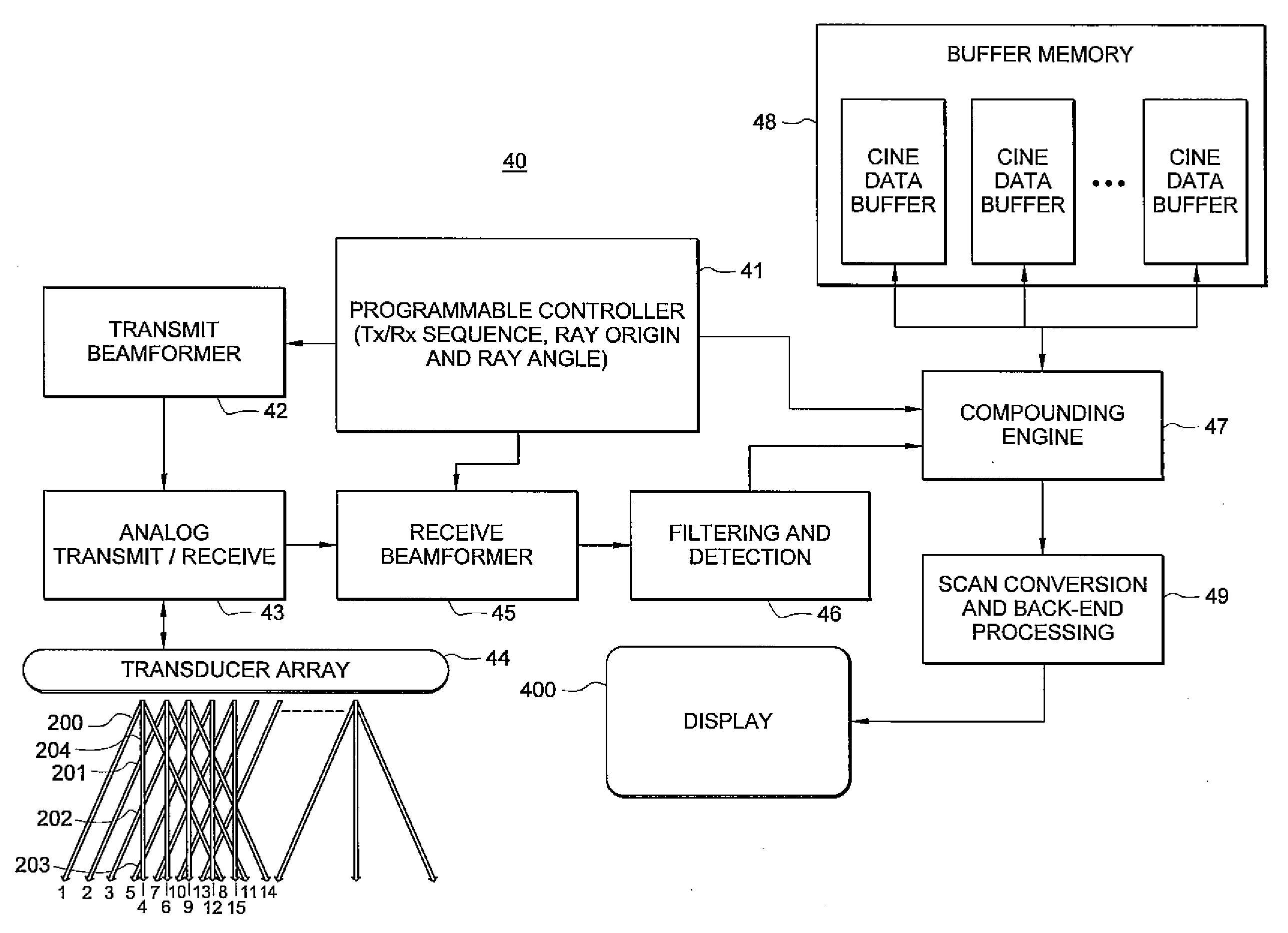
Image

Examples
Embodiment Construction
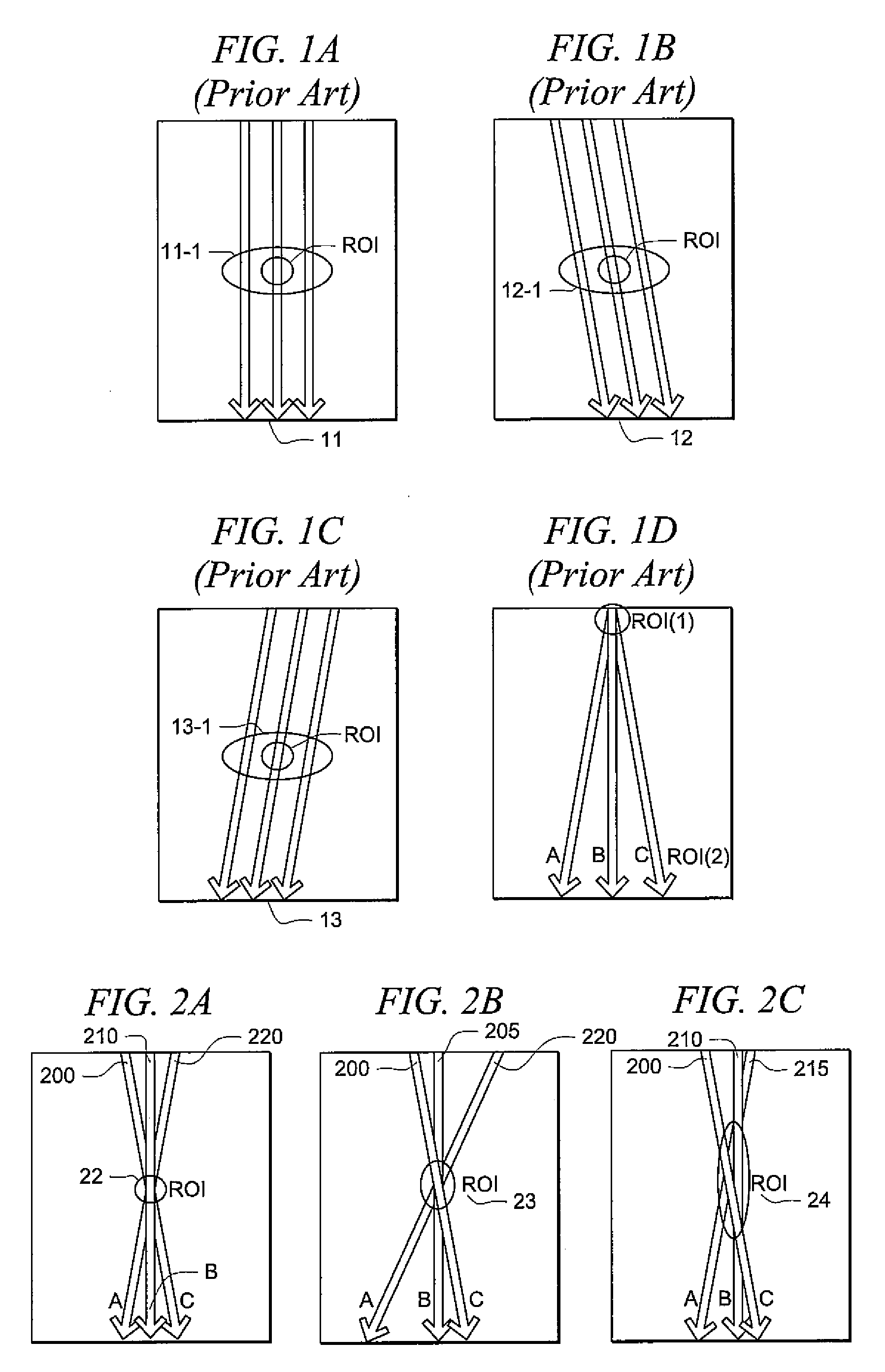
[0014]FIGS. 1A through 1C show examples of prior art frame interleaved spatial compounding. In FIG. 1A the beam rays are steered straight, while in FIGS. 1B and 1C the beam rays are steered left and right, respectively. This demonstrates the most common spatial compounding ray firing sequence which consists of acquiring separate frames for each steer direction. For example, frame 11 shows a full frame (only three rays of which are actually drawn) of straight rays 11-1 followed by full frame 12 of steered left rays 12-1 then by a full frame 13 of steered right rays 13-1. These three frames are then compounded together to form a final image. This compounding is difficult because the target may have moved between frames and thus the target will appear different for subsequent frames. In order to achieve the best image it is important to make sure that the different frames are aligned to each other before combining. In some cases extra post-processing is done to modify the frames before...
PUM
 Abstract
Description
Claims
Application Information